Status Register ST1
2-34
2.4 Status Register ST1
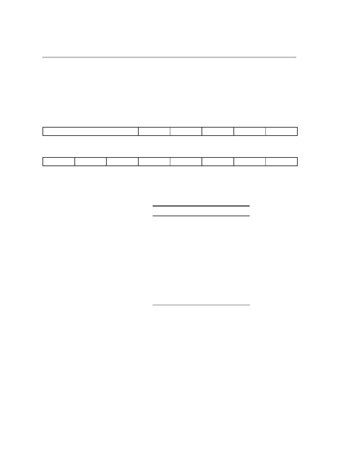
The following figure shows the bit fields of status register ST1. All of these bit
fields are modified in the decode 2 phase of the pipeline. Detailed descriptions
of these bits follow the figure.
Figure 2−11.Bit Fields of Status Register 1 (ST1)
15 13 12 11 10 9 8
ARP XF M0M1MAP Reserved OBJMODE AMODE
R/W-000 R/W−0 R/W−1 R/W−0 R/W−0 R/W−0
76543210
IDLESTAT
EALLOW LOOP SPA VMAP PAGE0 DBGM INTM
R−0 R/W−0R−0 R/W−0 R/W−1 R/W−0 R/W−1 R/W−1
ARP
Bits 15−13
Auxiliary register pointer. This 3-bit field points to the current auxiliary register. This is one
of the 32-bit auxiliary registers (XAR0−XAR7). The mapping of ARP values to auxiliary reg-
isters is as follows:
ARP
Selected Auxiliary Register
000 XAR0 (selected at reset)
001 XAR1
010 XAR2
011 XAR3
100 XAR4
101 XAR5
110 XAR6
111
XAR7
XF
Bit 12
XF status bit. This bit reflects the current state of the XFS output signal, which is com-
patible to the C2XLP CPU. This bit is set by the ”SETC XF” instruction. This bit is
cleared by the ”CLRC XF” instruction. The pipeline is not flushed when setting or clear-
ing this bit using the given instructions. This bit can be saved and restored by interrupts
and when restoring the ST1 register. This bit is set to 0 on reset.
M0M1MAP
Bit 11
M0 and M1 mapping mode bit. The M0M1MAP bit should always remain set to 1 in
the C28x object mode. This is the default value at reset. The M0M1MAP bit may be set
low when operating in C27x-compatible mode. The effect of this bit, when low, is to
swap the location of blocks M0 and M1 only in program space and to set the stack
pointer default reset value to 0x000. C28x mode users should never set this bit to 0.