Maskable Interrupts: INT1−INT14, DLOGINT, and RTOSINT
3-9CPU Interrupts and Reset
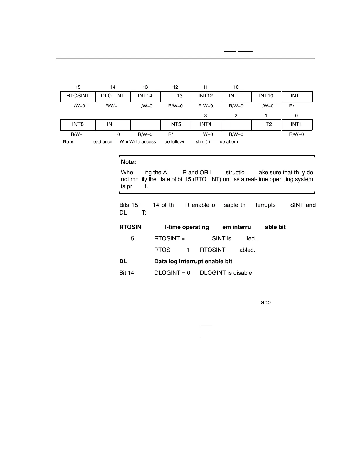
Figure 3−2. Interrupt Enable Register (IER)
15
14
13
12
11
10
9
8
RTOSINT
DLOGINT
INT14
INT13
INT12
INT11
INT10
INT9
R/W−0
R/W−0
R/W−0
R/W−0
R/W−0
R/W−0
R/W−0
R/W−0
7
6
5
4
3
2
1
0
INT8
INT7
INT6
INT5
INT4
INT3
INT2
INT1
R/W−0
R/W−0
R/W−0
R/W−0
R/W−0
R/W−0
R/W−0
R/W−0
ÁÁÁÁÁÁÁÁÁÁÁÁÁÁÁÁÁÁÁÁÁÁÁÁÁÁÁÁÁ
ÁÁÁÁÁÁÁÁÁÁÁÁÁÁÁÁÁÁÁÁÁÁÁÁÁÁÁÁÁ
Note: R = Read access; W = Write access; value following dash (−) is value after reset.
Note:
When using the AND IER and OR IER instructions, make sure that they do
not modify the state of bit 15 (RTOSINT) unless a real-time operating system
is present.
Bits 15 and 14 of the IER enable or disable the interrupts RTOSINT and
DLOGINT:
RTOSINT Real-time operating system interrupt enable bit
Bit 15 RTOSINT = 0 RTOSINT is disabled.
RTOSINT = 1 RTOSINT is enabled.
DLOGINT Data log interrupt enable bit
Bit 14 DLOGINT = 0 DLOGINT is disabled.
DLOGINT = 1 DLOGINT is enabled.
For bits INT1−INT14, the following general description applies:
INTx Interrupt x enable bit (x = 1, 2, 3, ..., or 14)
Bit (x−1) INTx = 0 INTx
is disabled.
INTx = 1 INTx
is enabled.
Figure 3−3 shows the DBGIER, which is used only when the CPU is halted in
real-time emulation mode. An interrupt enabled in the DBGIER is defined as
a time-critical interrupt. When the CPU is halted in real-time mode, the only in-
terrupts that are serviced are time-critical interrupts that are also enabled in
the IER. If the CPU is running in real-time emulation mode, the standard inter-
rupt-handling process is used and the DBGIER is ignored.