Maskable Interrupts: INT1−INT14, DLOGINT, and RTOSINT
3-10
As with the IER, you can read the DBGIER to identify enabled or disabled inter-
rupts and write to the DBGIER to enable or disable interrupts. To enable an
interrupt, set its corresponding bit to 1. To disable an interrupt, set its corre-
sponding bit to 0. Use the PUSH DBGIER instruction to read from the DBGIER
and the POP DBGIER instruction to write to the DBGIER. At reset, all the
DBGIER bits are set to 0.
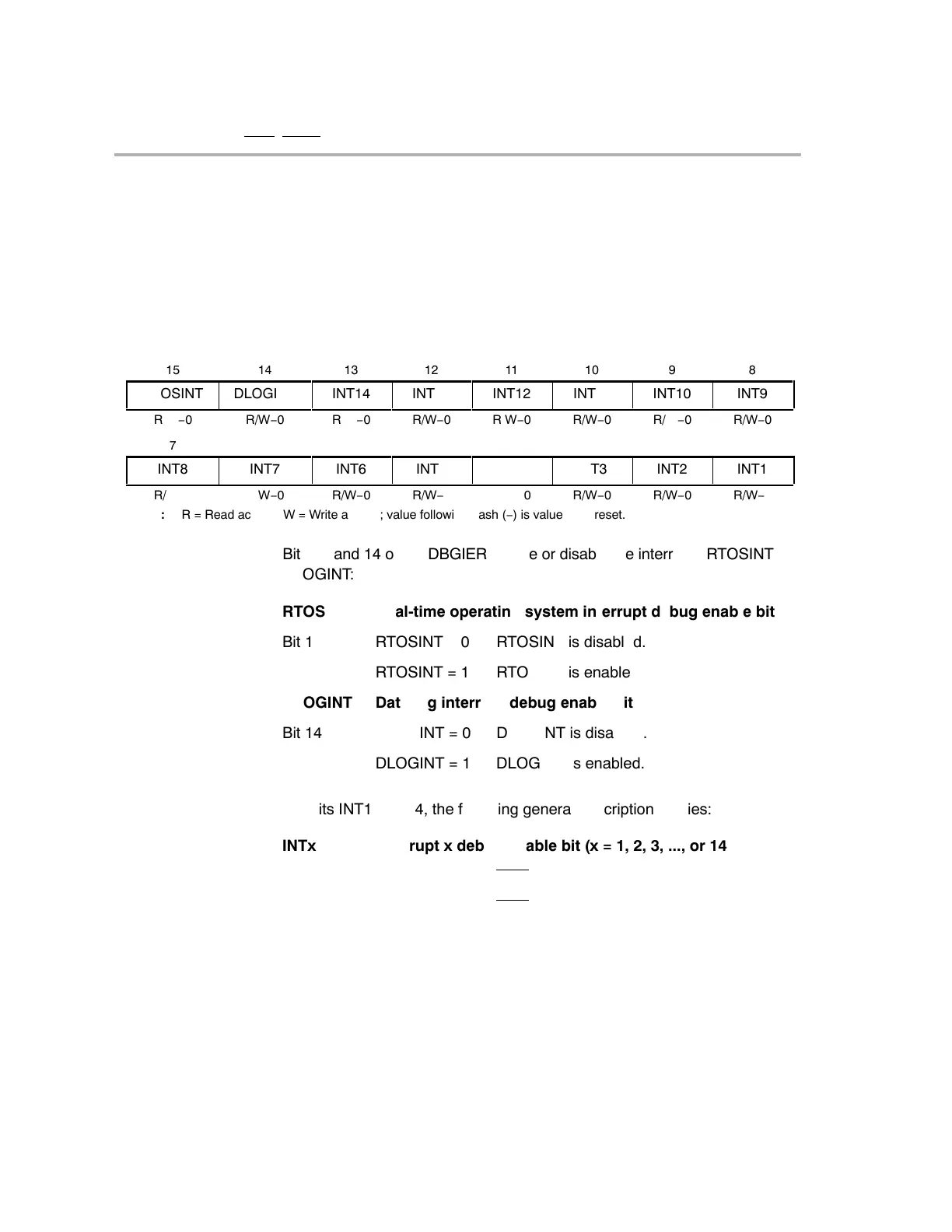
Figure 3−3. Debug Interrupt Enable Register (DBGIER)
15
14
13
12
11
10
9
8
RTOSINT
ÁÁÁ
DLOGINT
ÁÁ
INT14
ÁÁ
INT13
ÁÁÁ
INT12
ÁÁ
INT11
ÁÁ
INT10
ÁÁÁ
INT9
R/W−0
R/W−0
R/W−0
R/W−0
R/W−0
R/W−0
R/W−0
R/W−0
7
6
5
4
3
2
1
0
INT8
INT7
INT6
INT5
INT4
INT3
INT2
INT1
R/W−0
R/W−0
R/W−0
R/W−0
R/W−0
R/W−0
R/W−0
R/W−0
ÁÁÁÁÁÁÁÁÁÁÁÁÁÁÁÁÁÁÁÁÁÁÁÁÁÁÁÁÁ
Note: R = Read access; W = Write access; value following dash (−) is value after reset.
Bits 15 and 14 of the DBGIER enable or disable the interrupts RTOSINT and
DLOGINT:
RTOSINT Real-time operating system interrupt debug enable bit
Bit 15 RTOSINT = 0 RTOSINT is disabled.
RTOSINT = 1 RTOSINT is enabled.
DLOGINT Data log interrupt debug enable bit
Bit 14 DLOGINT = 0 DLOGINT is disabled.
DLOGINT = 1 DLOGINT is enabled.
For bits INT1−INT14, the following general description applies:
INTx Interrupt x debug enable bit (x = 1, 2, 3, ..., or 14)
Bit (x−1) INTx = 0 INTx
is disabled.
INTx = 1 INTx
is enabled.