Debug Interface
7-3Emulation Features
7.2 Debug Interface
The target-level TI debug interface uses the five standard IEEE 1149.1 (JTAG)
signals (TRST, TCK, TMS, TDI, and TDO) and the two TI extensions (EMU0
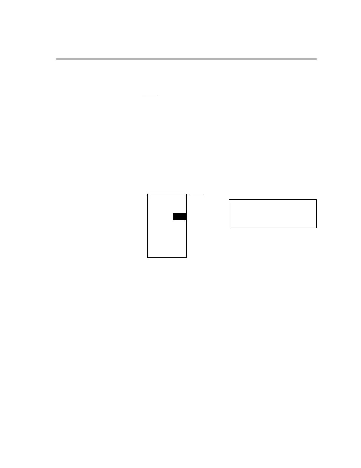
and EMU1). Figure 7−1 shows the 14-pin JTAG header that is used to inter-
face the target to a scan controller, and Table 7−1 (page 7-4) defines the pins.
As shown in the figure, the header requires more than the five JTAG signals
and the TI extensions. It also requires a test clock return signal (TCK_RET),
the target supply (V
CC
) and ground (GND). TCK_RET is a test clock out of the
scan controller and into the target system. The target system uses TCK_RET
if it does not supply its own test clock (in which case TCK would simply not be
used). In many target systems, TCK_RET is simply connected to TCK and
used as the test clock.
Figure 7−1. JTAG Header to Interface a Target to the Scan Controller
TDI 3 4 GND
TDO 7 8 GND
TMS 1 2 TRST
TCK_RET 9 10 GND
TCK 11 12 GND
Header dimensions:
Pin-to-pin spacing: 0.100 in. (X,Y)
Pin width: 0.025-in. square post
Pin length: 0.235-in. nominal
PD (V
CC
)5 6 No pin (key)
EMU0 13 14 EMU1