Maskable Interrupts: INT1−INT14, DLOGINT, and RTOSINT
3-7CPU Interrupts and Reset
Once an interrupt has been requested and properly enabled, the CPU pre-
pares for and then executes the corresponding interrupt service routine. For
a detailed description of this process, see section 3.4.
Table 3−2. Requirements for Enabling a Maskable Interrupt
Interrupt-Handling Process Interrupt Enabled If ...
Standard INTM = 0 and bit in IER is 1
DSP in real-time mode and CPU halted Bit in IER is 1 and bit in DBGIER is 1
As an example of varying interrupt-enable requirements, suppose you want
interrupt INT5
enabled. This corresponds to bit 4 in the IER and bit 4 in the
DBGIER. Usually, INT5 is enabled if INTM = 0 and IER(4) = 1. In real-time
emulation mode with the CPU halted, INT5
is enabled if IER(4) = 1 and
DBGIER(4) = 1.
3.3.1 CPU Interrupt Flag Register (IFR)
Figure 3−1 shows the IFR. If a maskable interrupt is pending (waiting for ap-
proval from the CPU), the corresponding IFR bit is 1; otherwise, the IFR bit is
0. To identify pending interrupts, use the PUSH IFR instruction and then test
the value on the stack. Use the OR IFR instruction to set IFR bits, and use the
AND IFR instruction to clear pending interrupts. When a hardware interrupt is
serviced, or when an INTR instruction is executed, the corresponding IFR bit
is cleared. All pending interrupts are cleared by the AND IFR, #0 instruction
or by a hardware reset.
Notes:
When an interrupt is requested by the TRAP instruction, if the corresponding
IFR bit is set, the CPU does not clear it automatically. If an application re-
quires that the IFR bit be cleared, the bit must be cleared in the interrupt ser-
vice routine.
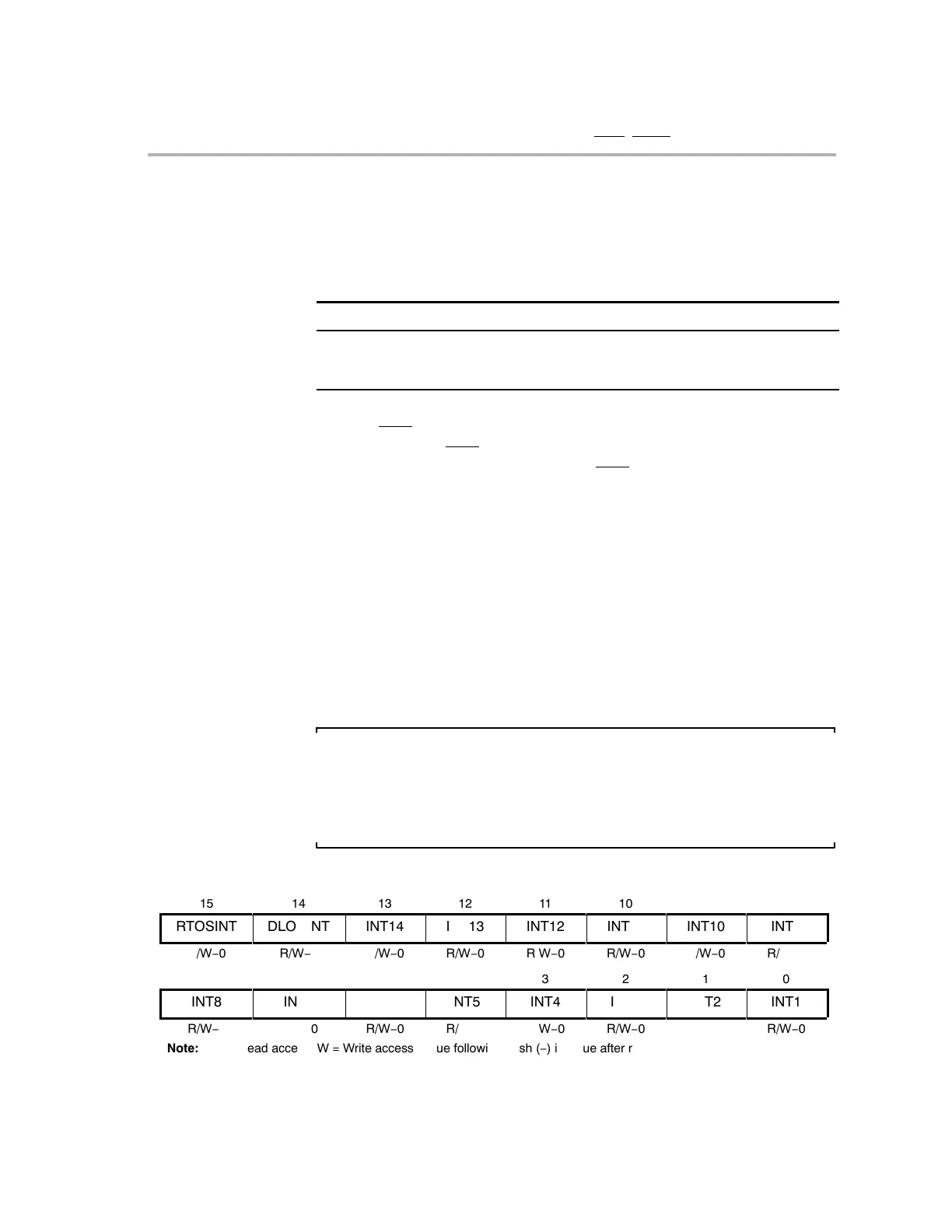
Figure 3−1. Interrupt Flag Register (IFR)
15
14
13
12
11
10
9
8
RTOSINT
DLOGINT
INT14
INT13
INT12
INT11
INT10
INT9
R/W−0
R/W−0
R/W−0
R/W−0
R/W−0
R/W−0
R/W−0
R/W−0
7
6
5
4
3
2
1
0
INT8
INT7
INT6
INT5
INT4
INT3
INT2
INT1
R/W−0
R/W−0
R/W−0
R/W−0
R/W−0
R/W−0
R/W−0
R/W−0
ÁÁÁÁÁÁÁÁÁÁÁÁÁÁÁÁÁÁÁÁÁÁÁÁÁÁÁÁÁ
ÁÁÁÁÁÁÁÁÁÁÁÁÁÁÁÁÁÁÁÁÁÁÁÁÁÁÁÁÁ
Note: R = Read access; W = Write access; value following dash (−) is value after reset.