Nonmaskable Interrupts
3-18
3.5.2 TRAP Instruction
You can use the TRAP instruction to initiate any interrupt, including one of the
user-defined software interrupts (see USER1−USER12 in Table 3−1 on page
3-4). The TRAP instruction refers to one of the 32 interrupts by a number from
0 to 31. For example, you can execute the interrupt service routine for INT1
by using the following instruction:
TRAP #1
Regardless of whether the interrupt has bits set in the IFR and IER, neither the
IFR nor the IER is affected by this instruction. Figure 3−5 shows a functional
flow chart for an interrupt initiated by the TRAP instruction. For more details
about the TRAP instruction, see Chapter 6, C28x Assembly Language Instruc-
tions.
Note:
The TRAP #0 instruction does not initiate a full reset. It only forces execution
of the interrupt service routine that corresponds to the RESET interrupt vec-
tor.
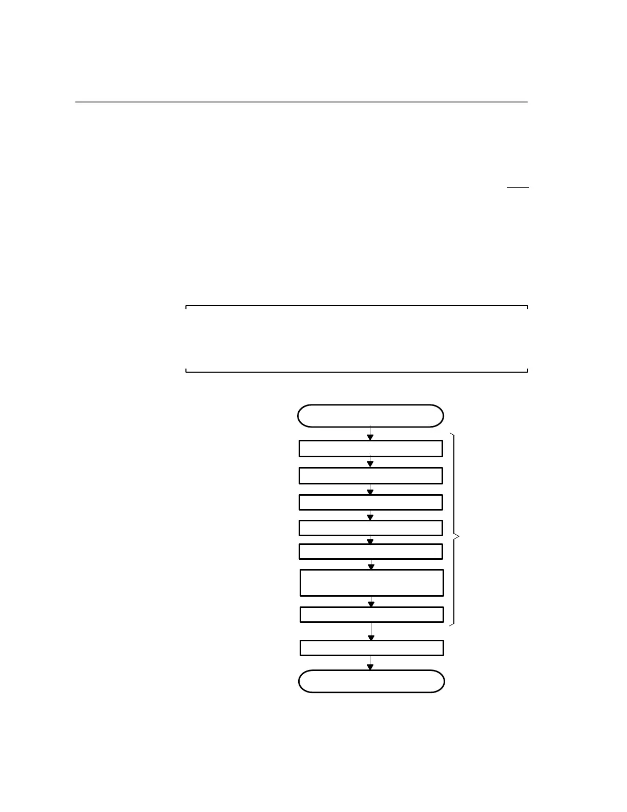
Figure 3−5. Functional Flow Chart for an Interrupt Initiated by the TRAP Instruction
TRAP instruction fetched
Increment and temporarily store PC.
Fetch interrupt vector.
Perform automatic context save.
Increment SP by 1.
Empty the pipeline.
Set INTM and DBGM. Clear LOOP,
EALLOW, and IDLESTAT.
Execute interrupt service routine.
Program continues
Load PC with fetched vector.
This sequence
protected from
INTM bit, IFR,
interrupts
IER, and DBGIER
ignored and not affected