Registers
AMODE == 0, the page size is reduced by half. This was done to accommo-
date other useful addressing modes.
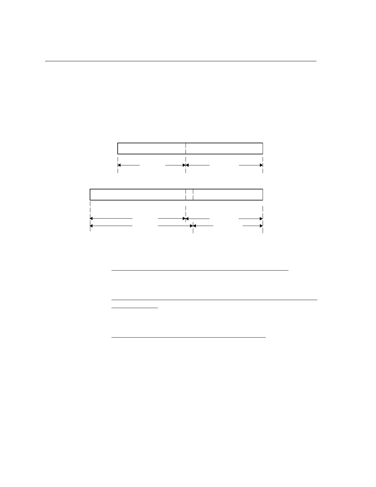
The mapping of the direct addressing modes between the C2xLP and the
C28x is as shown in Figure C−2.
Figure C−2. Direct Addressing Mode Mapping
C28x
21 2 0
22 bit address
21 2 015 765
AMODE = 1:
AMODE = 0:
DP (15:1)
DP (15:0)
7-bit offset
6-bit offset
15
C2xLP
15
16 bit address
15
76
0
0
DP (8:0)
7-bit offset
Using the previous example, the assembler/linker will initialize the DP and
offset values as follows on the C28x:
C2xLP Original Source Mode (”−v28 −m20” mode, AMODE == 1)
LDP #VarA ; DP(15:0) = 0x3456/128 << 1 = 0x00D1
LACL VarA ; 7-bit offset = 0x3456 & 0x007F = 0x56
Equivalent C28x Mnemonics (after C2xLP source is reassembled with the
C28x assembler)
MOVZ DP,#VarA ; DP(15:0) = 0x3456/128 << 1 = 0x00D1
MOVU ACC,@@VarA ; 7-bit offset = 0x3456 & 0x007F = 0x56
C28x Addressing Mode (”−v28” mode, AMODE == 0)
MOVZ DP,#VarA ; DP(15:0) = 0x3456/64 = 0x00D1
MOVU ACC,@VarA ; 6-bit offset = 0x3456 & 0x003F = 0x16
Note: When using C28x syntax, the 128 word data page is indicated by using the double ”@@” symbol. The 64 word data page
is indicated by the single ”@” symbol. This helps the user and assembler to track which mode is being used.