Standard Operation for Maskable Interrupts
3-15CPU Interrupts and Reset
ÁÁÁÁÁÁÁÁÁÁÁÁÁÁÁÁÁÁÁÁÁÁÁÁÁÁÁÁÁÁ
ÁÁÁÁÁÁÁÁÁÁÁÁÁÁÁÁÁÁÁÁÁÁÁÁÁÁÁÁÁÁ
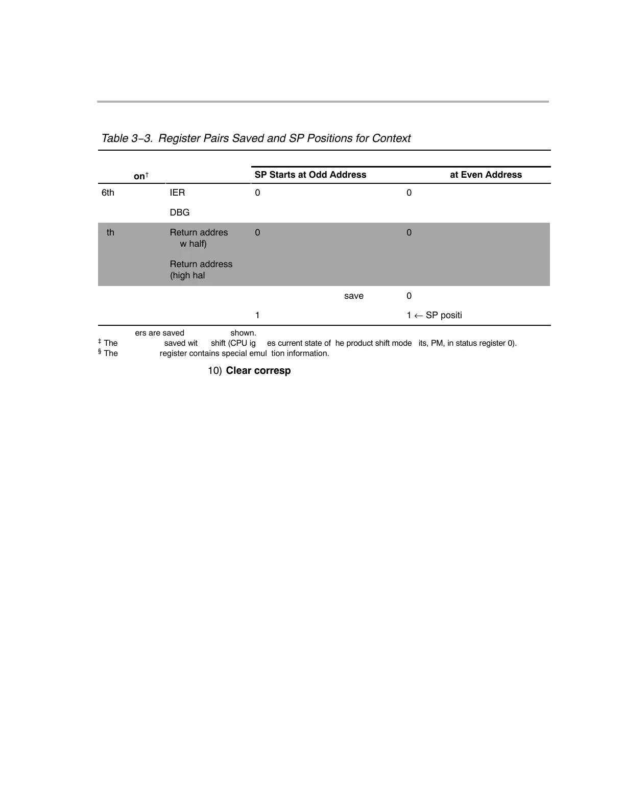
Table 3−3. Register Pairs Saved and SP Positions for Context Saves (Continued)
ÁÁÁÁÁÁÁÁÁÁÁÁÁÁÁÁÁÁÁÁ
ÁÁÁÁÁÁÁÁÁÁÁÁÁÁÁÁÁÁÁÁ
Bit 0 of Storage Address
Register
Pairs
Save
Operation
†
SP Starts at Even Address
SP Starts at Odd Address
Register
Pairs
Save
Operation
†
6th
IER
0
0
ÁÁÁ
ÁÁÁÁÁ
DBGSTAT
§
ÁÁÁÁÁÁÁÁ
1
ÁÁÁÁÁÁÁÁÁ
1
7th Return address
(low half)
0 0
Return address
(high half)
1 1
0 ← SP position after save 0
1 1 ← SP position after save
†
All registers are saved as pairs, as shown.
‡
The P register is saved with 0 shift (CPU ignores current state of the product shift mode bits, PM, in status register 0).
§
The DBGSTAT register contains special emulation information.
10) Clear corresponding IER bit. After the IER register is saved on the stack
in step 9, the CPU clears the IER bit that corresponds to the interrupt being
handled. This prevents reentry into the same interrupt. If you want to nest
occurrences of the interrupt, have the ISR set that IER bit again.
11) Set INTM and DBGM. Clear LOOP, EALLOW, and IDLESTAT. All these
bits are in status register ST1. By setting INTM to 1, the CPU prevents
maskable interrupts from disturbing the ISR. If you wish to nest interrupts,
have the ISR clear the INTM bit. By setting DBGM to 1, the CPU prevents
debug events from disturbing time-critical code in the ISR. If you do not
want debug events blocked, have the ISR clear DBGM.
The CPU clears LOOP, EALLOW, and IDLESTAT so that the ISR operates
within a new context.
12) Load PC with fetched vector. The PC is loaded with the interrupt vector
that was fetched in step 7. The vector forces program control to the ISR.
13) Execute interrupt service routine. Here is where the CPU executes the
program code you have prepared to handle the interrupt. A typical ISR is
shown in Example 3−1.
Although a number of register values are saved automatically in step 10, if
the ISR uses other registers, you may need to save the contents of these
registers at the beginning of the ISR. These values must then be restored
before the return from the ISR. The ISR in Example 3−1 saves and re-
stores auxiliary registers AR1H:AR0H, XAR2−XAR7, and the temporary
register XT.