Analog-to-Digital Converter (ADC)
6 - 6 TMS320F2837xD Microcontroller Workshop - Analog Subsystem
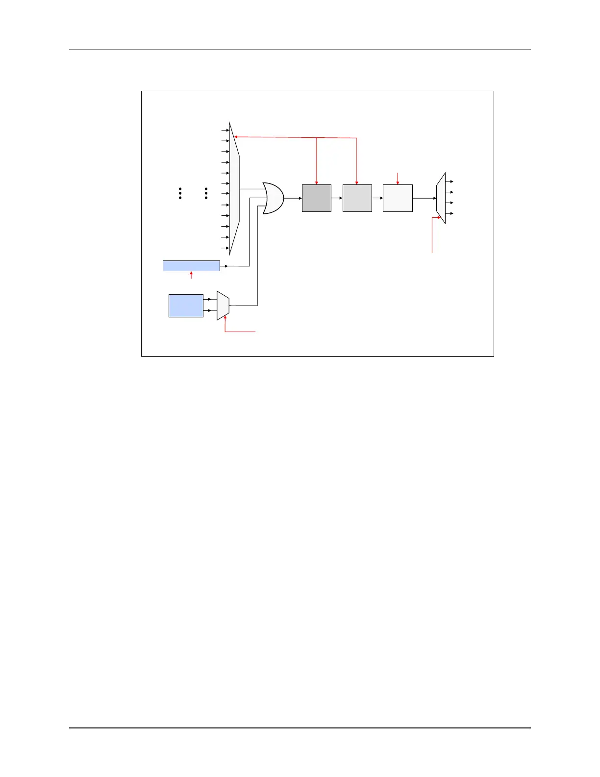
ADC SOCx Functional Diagram
This block diagram is replicated 16 times
ADCINT1
ADCINT2
Re-Trigger
ADCINT1
ADCINT2
ADCINT3
ADCINT4
Channel
Select
Sample
Window
Result
Register
S
O
C
x
E
O
C
x
ADCSOCxCTL
ADCINTSOCSEL1
ADCINTSOCSEL2
INTSELxNy
ADCRESULTx
Software Trigger
TINT0 (CPU1 Timer 0)
TINT1 (CPU1 Timer 1)
TINT2 (CPU1 Timer 2)
ADCEXTSOC (GPIO)
SOCA/C (ePWM1)
SOCB/D (ePWM1)
SOCA/C (ePWM12)
SOCB/D (ePWM12)
TINT0 (CPU2 Timer 0)
TINT1 (CPU2 Timer 1)
TINT2 (CPU2 Timer 2)
T
r
i
g
g
e
r
ADCSOCFRC1
The figure above is a conceptual view highlighting a single ADC start-of-conversion functional
flow from triggering to interrupt generation. This figure is replicated 16 times and the red text
indicates the register names.

 Loading...


