Reset and Boot Process
TMS320F2837xD Microcontroller Workshop - Reset and Interrupts 4 - 5
Reset - Bootloader
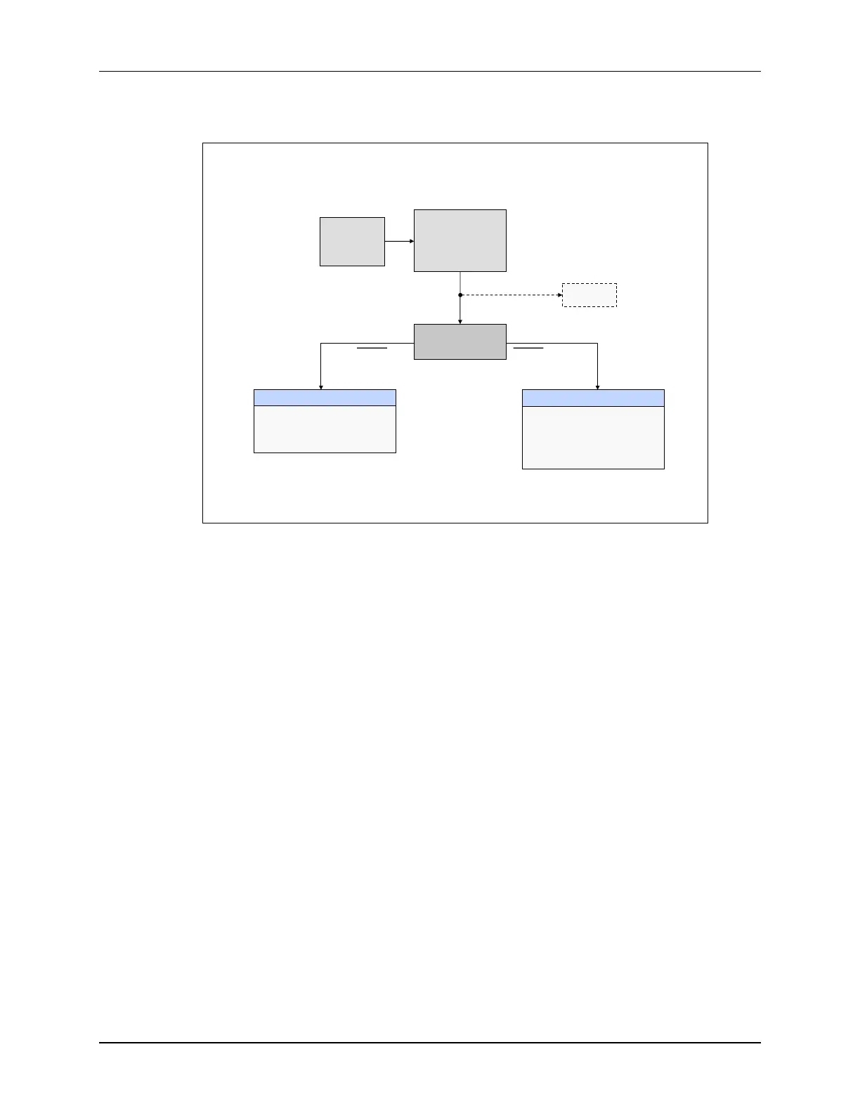
Reset – Bootloader
TRST = JTAG Test Reset
EMU_BOOTCTRL register located in PIE RAM at 0x000D00
Z1-BOOTCTRL register located in OTP at 0x07801E
Z2-BOOTCTRL register located in OTP at 0x07821E
Reset vector
fetched from
boot ROM
0x3F FFC0
Emulation Boot
Boot determined by
EMU_BOOTCTRL:
EMU_KEY and EMU_BMODE
Stand-alone Boot
Boot determined by
2 GPIO pins and
Zx-BOOTCTRL:
OTP_KEY and OTP_BMODE
TRST = 1 TRST = 0
Reset
ENPIE = 0
INTM = 1
YES
NO
Emulator
Connected ?
CPU2
CPU2 held in
reset until
released by
CPU1.
When the device is reset, the peripheral interrupt expansion block, also known as the PIE block,
and the master interrupt switch INTM are disabled. This prevents any interrupts during the boot
process. The program counter is set to 0x3FFFC0, where the reset vector is fetched. In the boot
code the JTAG Test Reset line (TRST line) is checked to determine if the emulator is connected.
If the emulator is connected, then the boot process follows the Emulation Boot mode flow. In
Emulation Boot mode, the boot is determined by the EMU_BOOTCTRL register located in the
PIE RAM. Specific details about the boot flow are then determined by the EMU_KEY and
EMU_BMODE bit fields in the EMU_BOOTCTRL register.
If the emulator is not connected, the boot process follows the Stand-alone Boot mode flow. In
Stand-alone Boot mode, the boot is determined by two GPIO pins and the Z1-BOOTCTRL and
Z2-BOOTCTRL registers located in the OTP. Specific details about the boot flow are then deter-
mined by the OTP_KEY and OTP_BMODE bit fields in the Z1-BOOTCTRL and Z2-BOOTCTRL
registers.

 Loading...


