Interrupt Response - Hardware Sequence
Note: some actions occur simultaneously, none are interruptible
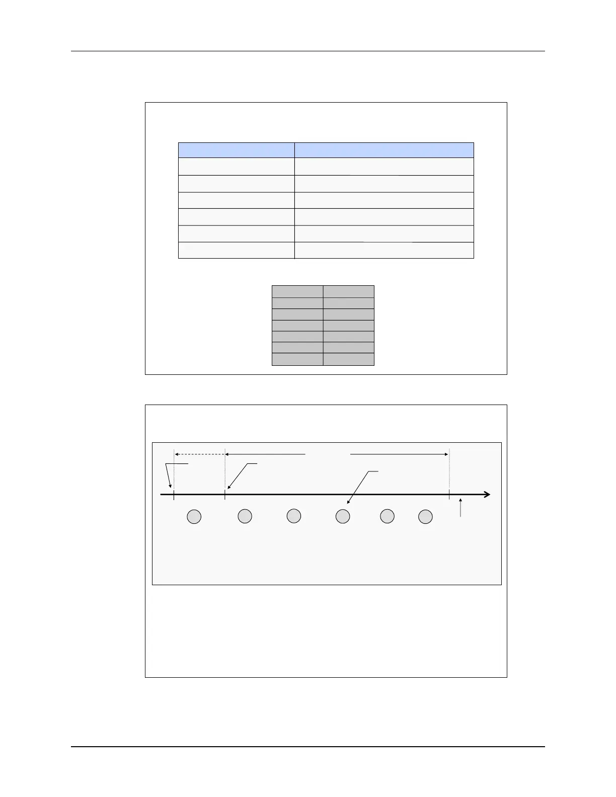
CPU Action Description
T ST0
AH AL
PH PL
AR1 AR0
DP ST1
DBSTAT IER
PC(msw) PC(lsw)
Registers → stack 14 Register words auto saved
0 → IFR (bit) Clear corresponding IFR bit
0 → IER (bit) Clear corresponding IER bit
1 → INTM/DBGM Disable global ints/debug events
Vector → PC Loads PC with int vector address
Clear other status bits Clear LOOP, EALLOW, IDLESTAT
Interrupt Latency
Latency
Depends on wait states, INTM, etc.
Maximum latency:
Recognition
delay (3), SP
alignment (1),
interrupt
placed in
pipeline
4
Minimum latency (to when real work occurs in the ISR):
Internal interrupts: 14 cycles
External interrupts: 16 cycles
Get vector
and place
in PC
(3 reg.
pairs
saved)
3
F1/F2/D1 of
ISR
instruction
(3 reg. pairs
saved)
3
Save
return
address
1
D2/R1/R2 of
ISR
instruction
3
Sync ext.
signal
(ext.
interrupt
only)
2
cycles
Assumes ISR in
internal RAM
Internal
interrupt
occurs
here
ext.
interrupt
occurs
here
ISR
instruction
executed
on next
cycle

 Loading...


