Lab 6: Analog-to-Digital Converter
6 - 28 TMS320F2837xD Microcontroller Workshop - Analog Subsystem
Lab 6: Analog-to-Digital Converter
Objective
The objective of this lab exercise is to become familiar with the programming and operation of the
on-chip analog-to-digital converter (ADC). The microcontroller (MCU) will be setup to sample a
single ADC input channel at a prescribed sampling rate and store the conversion result in a
circular memory buffer. In the second part of this lab exercise, the digital-to-analog converter
(DAC) will be explored.
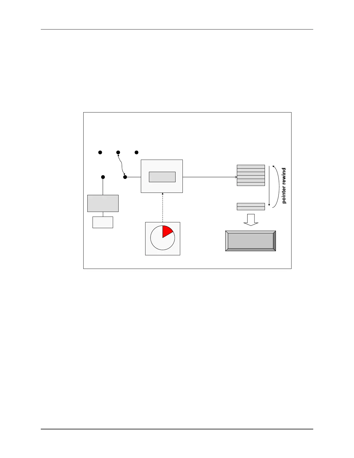
Lab 6: ADC Sampling
ADC-A
ADCINA0
RESULT0
...
data
memory
CPU copies result
to buffer during
ADC ISR
ePWM2
ePWM2 triggering
ADC on period match
using SOCA trigger every
20 µs (50 kHz)
GND
+3.3 V
(GPIO19)
Toggle
(GPIO18)
jumper
wire
View ADC
buffer PWM
samples
Code Composer
Studio
DAC-B
Sine
Table
Recall that there are three basic ways to initiate an ADC start of conversion (SOC):
1. Using software
a. SOCx bit (where x = 0 to 15) in the ADC SOC Force 1 Register (ADCSOCFRC1)
causes a software initiated conversion
2. Automatically triggered on user selectable conditions
a. CPU Timer 0/1/2 interrupt
b. ePWMxSOCA / ePWMxSOCB (where x = 1 to 12)
- ePWM underflow (CTR = 0)
- ePWM period match (CTR = PRD)
- ePWM underflow or period match (CTR = 0 or PRD)
- ePWM compare match (CTRU/D = CMPA/B/C/D)
c. ADC interrupt ADCINT1 or ADCINT2
- triggers SOCx (where x = 0 to 15) selected by the ADC Interrupt Trigger SOC
Select1/2 Register (ADCINTSOCSEL1/2)
3. Externally triggered using a pin
a. ADCSOC pin (GPIO/ADCEXTSOC)
One or more of these methods may be applicable to a particular application. In this lab exercise,
we will be using the ADC for data acquisition. Therefore, one of the ePWMs (ePWM2) will be
configured to automatically trigger the SOCA signal at the desired sampling rate (ePWM period
match CTR = PRD SOC method 2b above). The ADC end-of-conversion interrupt will be used to

 Loading...


