EasyManuals Logo

Texas Instruments TMS320F2837 D Series Workshop Guide And Lab Manual

Texas Instruments TMS320F2837 D Series
324 pages
To Next Page IconTo Next Page
To Previous Page IconTo Previous Page
Page #275 background image
Inter-Processor Communications
TMS320F2837xD Microcontroller Workshop - Dual-Core Inter-Processor Communications 11 - 5
CPU1 can read it. After the sending CPU writes a message it can inform the receiver CPU that it
is available through an interrupt or flag.
IPC Message Registers
Provides very simple and flexible messaging
Dedicated registers mapped to both CPU’s
The definition (what the register content
means) is up to the application software
TI’s IPC-Lite drivers use the IPC message
registers
Local Register
Name
Local
CPU
Remote
CPU
Remote Register
Name
IPCSENDCOM
R/W R
IPCRECVCOM
IPCSENDADDR
R/W R
IPCRECVADDR
IPCSENDDATA
R/W R
IPCRECVDATA
IPCREMOTEREPLY
R R/W
IPCLOCALREPLY
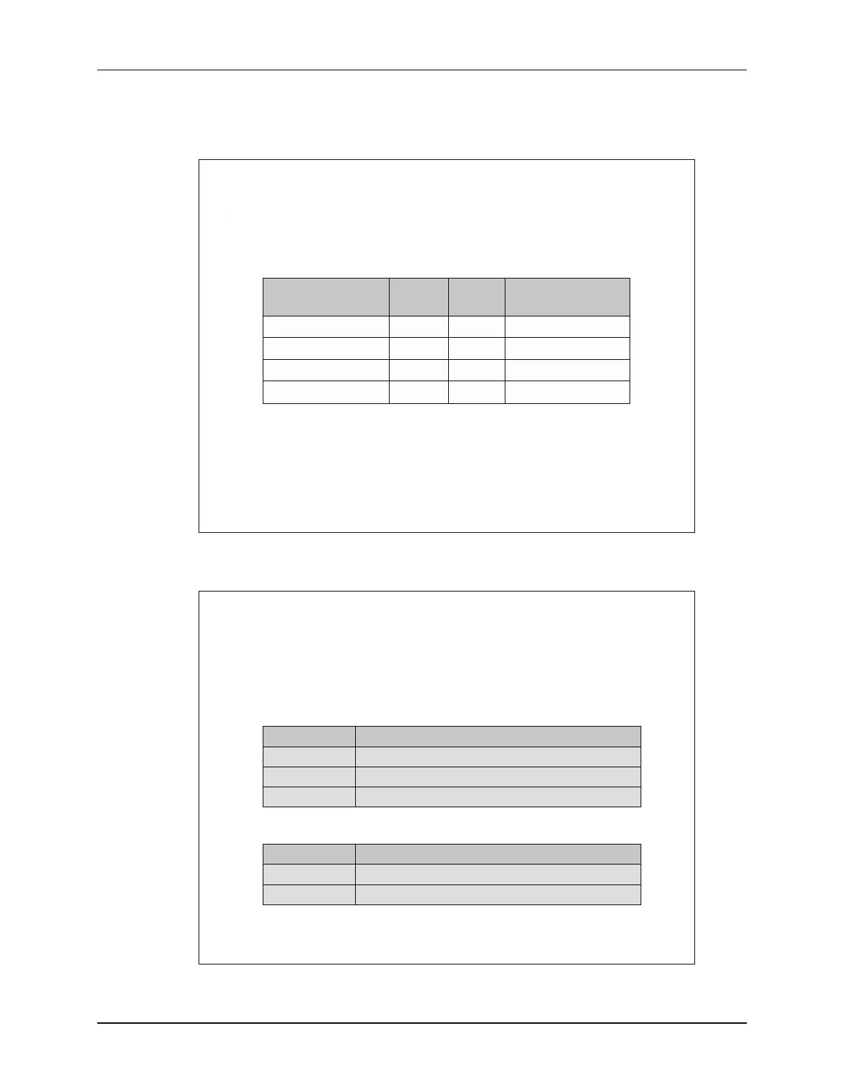
Interrupts and Flags
IPC Flags and Interrupts
CPU1 to CPU2: 32 flags with 4 interrupts (IPC0-3)
CPU2 to CPU1: 32 flags with 4 interrupts (IPC0-3)
Register
IPCSET
Message waiting (send
interrupt and/or set flag)
IPCFLG
Bit
is set by the “SET” register
IPCCLR
Clear the flag
Requesting CPU Set, Flag and Clear registers
Register
IPCSTS
Status (reflects the FLG
bit)
IPCACK
Clear
STS and FLG
Receiving CPU Status and Acknowledge registers

Table of Contents

Other manuals for Texas Instruments TMS320F2837 D Series

Questions and Answers:

Question and Answer IconNeed help?

Do you have a question about the Texas Instruments TMS320F2837 D Series and is the answer not in the manual?

Texas Instruments TMS320F2837 D Series Specifications

General IconGeneral
BrandTexas Instruments
ModelTMS320F2837 D Series
CategoryMicrocontrollers
LanguageEnglish

Related product manuals