Interrupts
TMS320F2837xD Microcontroller Workshop - Reset and Interrupts 4 - 19
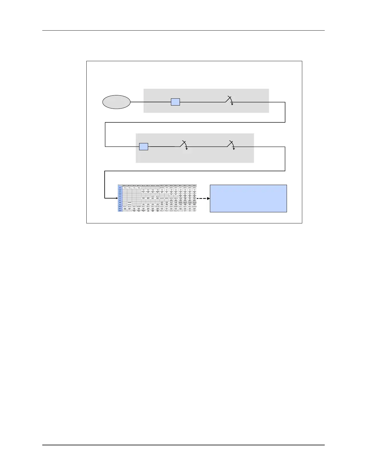
Interrupt Signal Flow – Summary
Interrupt Signal Flow – Summary
Peripheral
Interrupt
PIEIFRx
PIEIERx
INTx.y
PieCtrlRegs.PIEIERx.bit.INTxy = 1;
IER
INTM
IFR
asm(“ CLRC INTM”);
IER |= 0x0001;
0x0FFF;
1
1
Peripheral Interrupt Expansion (PIE) – Interrupt Group x
Core Interrupt Logic
PIE Vector Table
INTx.y name
interrupt void name(void)
{
}
•
•
•
DefaultIsr.c
Core
INTx
(For peripheral interrupts where x = 1 to 12, and y = 1 to 16)
In summary, the following steps occur during an interrupt process. First, a peripheral interrupt is
generated and the PIE interrupt flag register is set. If the PIE interrupt enable register is enabled,
then the core interrupt flag register will be set. Next, if the core interrupt enable register and
global interrupt mask is enabled, the PIE vector table will redirect the code to the interrupt service
routine.
 Loading...


