Interrupts
TMS320F2837xD Microcontroller Workshop - Reset and Interrupts 4 - 17
PIE Block Initialization
PIE Block Initialization
•
•
•
// CPU Initialization
InitPieCtrl();
•
•
•
Main.c
•
•
•
// Initialize PIE_RAM
memcpy( );
•
•
•
PieCtrl.c
// Enable PIE Block
PieCtrlRegs.
PIECTRL.bit.
ENPIE=1;
•
•
•
•
•
•
// Base Vectors
PieVect.c
PIE_VECT_TABLE
•
•
•
// Core INT1 re-map
// Core INT12 re-map
PIE RAM
Vectors
512w
(ENPIE = 1)
Boot ROM
Reset Vector
1
2
2
3
Memory Map
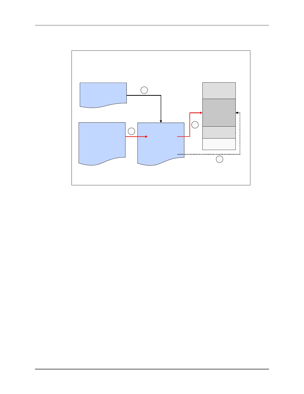
The interrupt vector table, as mapped in the PIE interrupt assignment table, is located in the
PieVect.c file. During processor initialization a function call to PieCtrl.c file is used to copy the
interrupt vector table to the PIE RAM and then the PIE module is enabled by setting ENPIE to ‘1’.
When the CPU receives an interrupt, the vector address of the ISR is fetched from the PIE RAM,
and the interrupt with the highest priority that is both flagged and enabled is executed. Priority is
determined by the location within the interrupt vector table. The lowest numbered interrupt has
the highest priority when multiple interrupts are pending.

 Loading...


