Creating a Linker Command File
TMS320F2837xD Microcontroller Workshop - Programming Development Environment 2 - 15
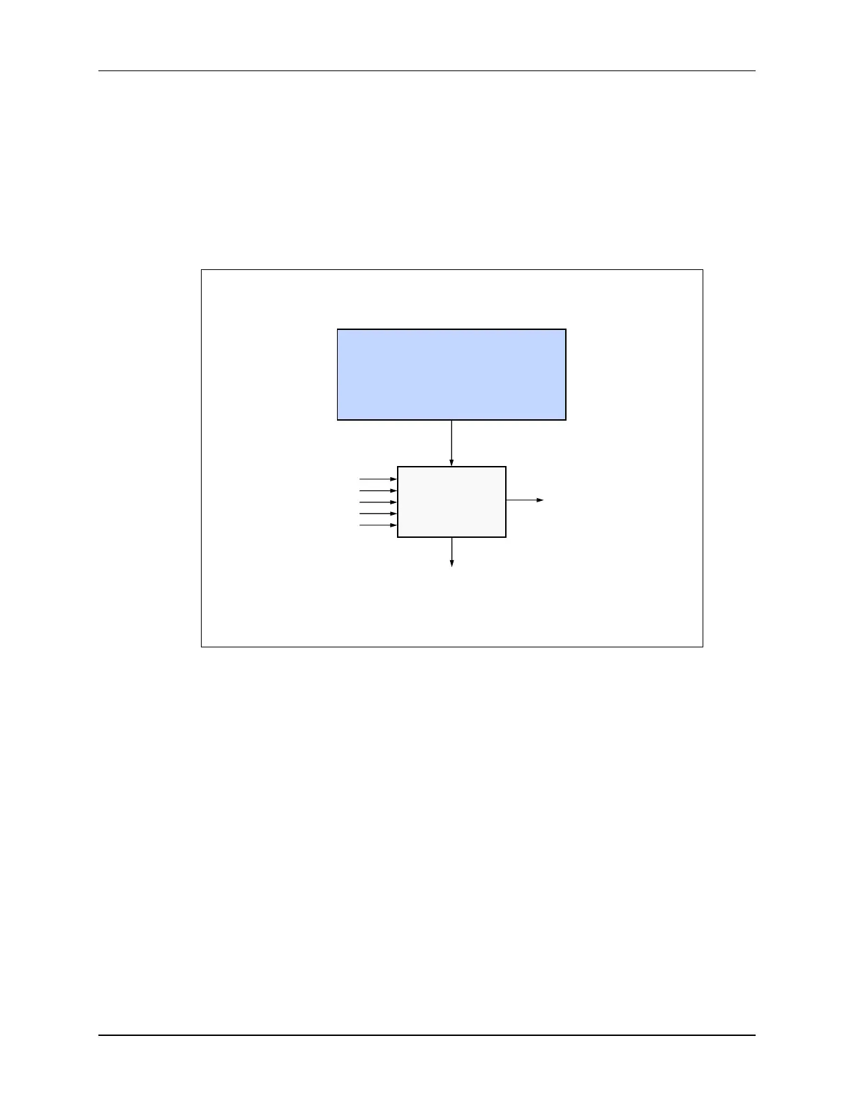
Linker Command Files (.cmd)
The linker concatenates each section from all input files, allocating memory to each section
based on its length and location as specified by the MEMORY and SECTIONS commands in the
linker command file. The linker command file describes the physical hardware memory and
specifies where the sections are placed in the memory. The file created during the link process is
a .out file. This is the file that will be loaded into the microcontroller. As an option, we can
generate a map file. This map file will provide a summary of the link process, such as the
absolute address and size of each section.
Linking
Linker
Link.cmd
.map
.obj
.out
Memory description
How to place s/w into h/w
Memory-Map Description
The MEMORY section describes the memory configuration of the target system to the linker.
The format is: Name: origin = 0x????, length = 0x????
For example, if you placed a 256Kw FLASH starting at memory location 0x080000, it would read:
MEMORY
{
FLASH: origin = 0x080000 , length = 0x040000
}
Each memory segment is defined using the above format. If you added RAMM0 and RAMM1, it
would look like:
MEMORY
{
RAMM0: origin = 0x000000 , length = 0x0400
RAMM1: origin = 0x000400 , length = 0x0400

 Loading...


