Creating a Linker Command File
2 - 14 TMS320F2837xD Microcontroller Workshop - Programming Development Environment
must be declared with a directive to reserve memory to contain its value. By their nature, no value
is assigned, instead they are loaded at runtime by the program.
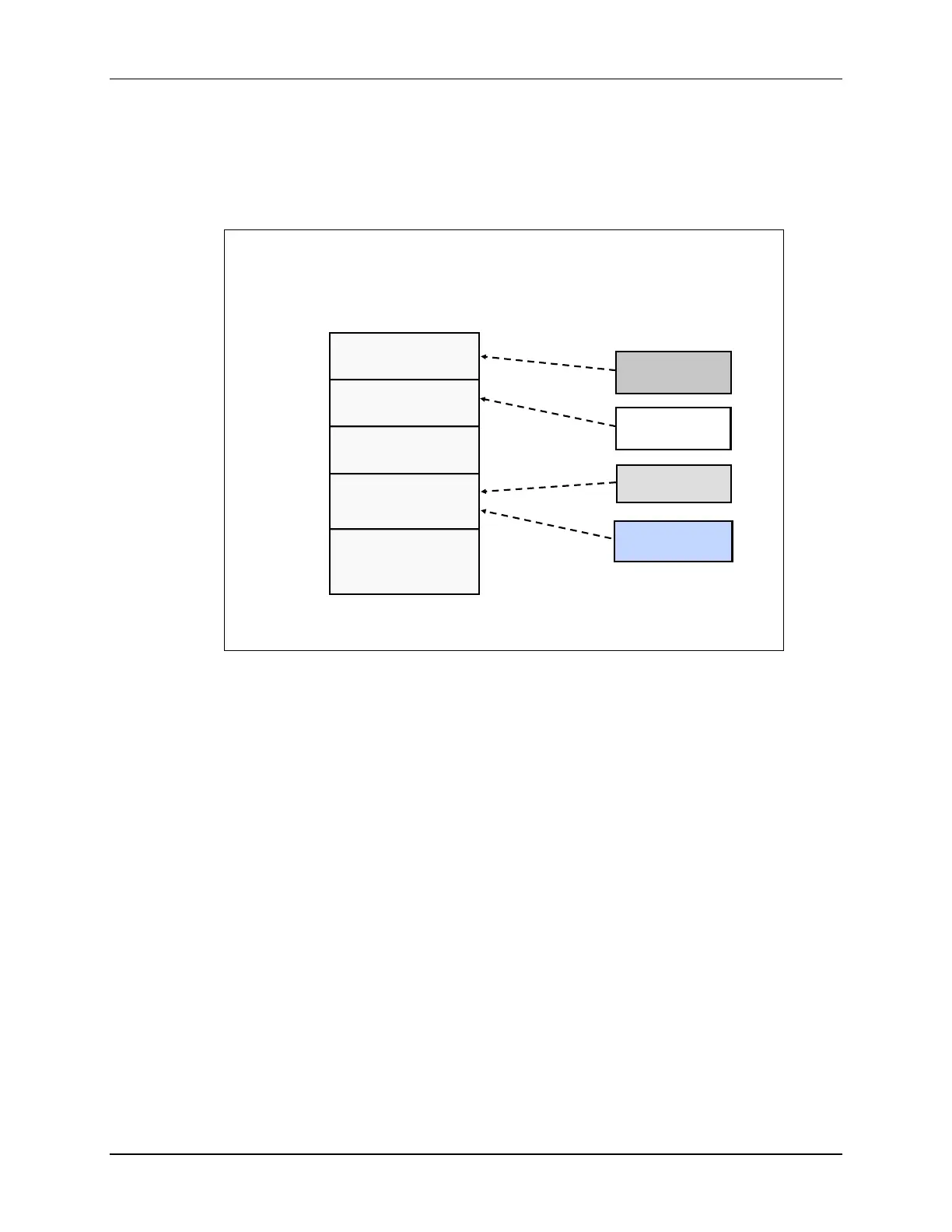
Next, we need to place the sections that were created by the compiler into the appropriate
memory spaces. The uninitialized sections, .ebss and .stack, need to be placed into RAM; while
the initialized sections, .cinit, and .txt, need to be placed into flash.
Placing Sections in Memory
.ebss
.cinit
.text
Memory
RAMM0
(0x400)
0x00 0000
0x08 0000
0x00 0400
RAMM1
(0x400)
FLASH
(0x40000)
Sections
.stack
Linking code is a three step process:
1. Defining the various regions of memory (on-chip RAM vs. FLASH vs. External Memory).
2. Describing what sections go into which memory regions
3. Running the linker with “build” or “rebuild”

 Loading...


