PWM Review
TMS320F2837xD Microcontroller Workshop - Control Peripherals 7 - 3
PWM Review
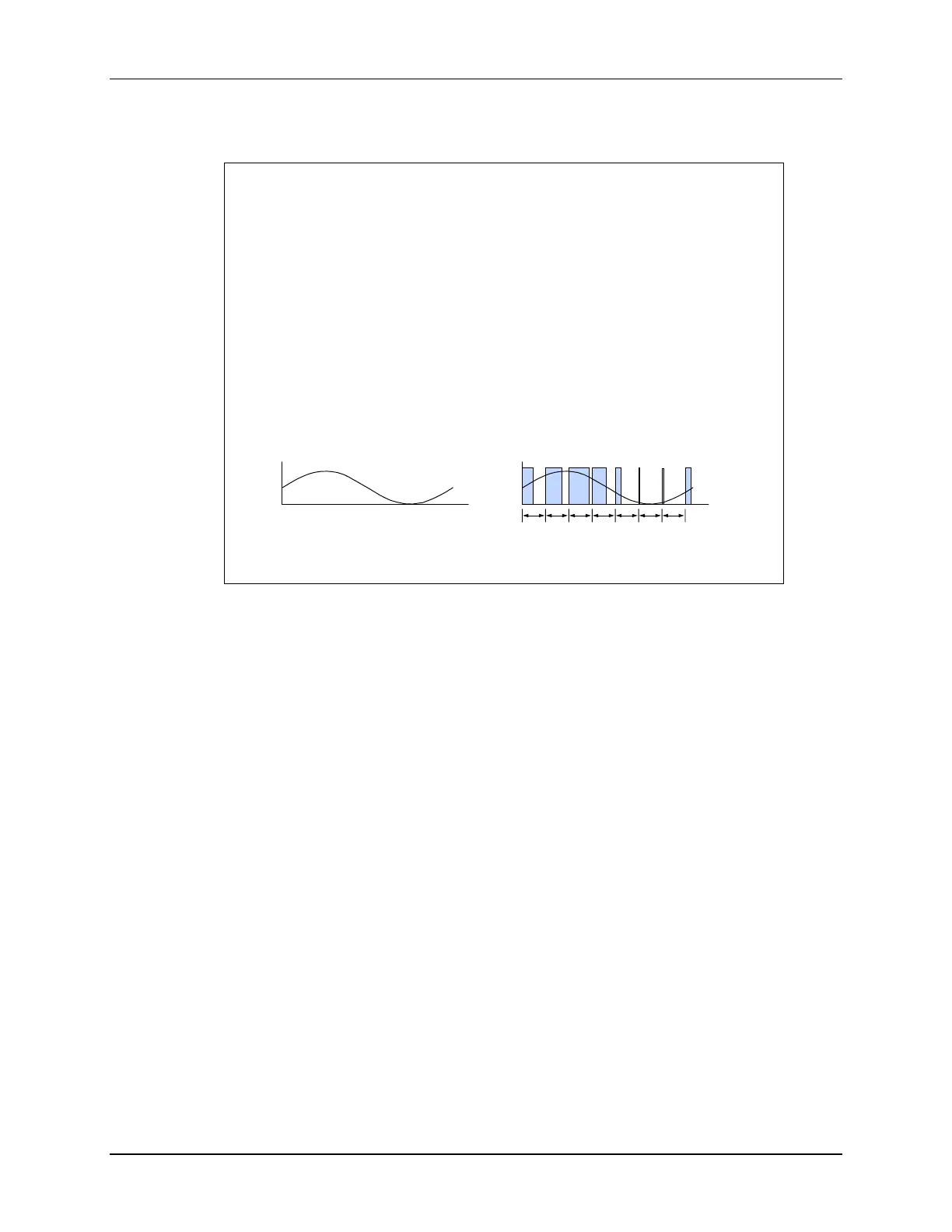
What is Pulse Width Modulation?
PWM is a scheme to represent a
signal as a sequence of pulses
fixed carrier frequency
fixed pulse amplitude
pulse width proportional to
instantaneous signal amplitude
PWM energy ≈ original signal energy
t
Original Signal
T
t
PWM representation
Pulse width modulation (PWM) is a method for representing an analog signal with a digital
approximation. The PWM signal consists of a sequence of variable width, constant amplitude
pulses which contain the same total energy as the original analog signal. This property is
valuable in digital motor control as sinusoidal current (energy) can be delivered to the motor using
PWM signals applied to the power converter. Although energy is input to the motor in discrete
packets, the mechanical inertia of the rotor acts as a smoothing filter. Dynamic motor motion is
therefore similar to having applied the sinusoidal currents directly.

 Loading...


