Lab 2: Linker Command File
TMS320F2837xD Microcontroller Workshop - Programming Development Environment 2 - 19
Lab 2: Linker Command File
Objective
Use a linker command file to link the C program file (Lab2.c) into the system described below.
Lab 2: Linker Command File
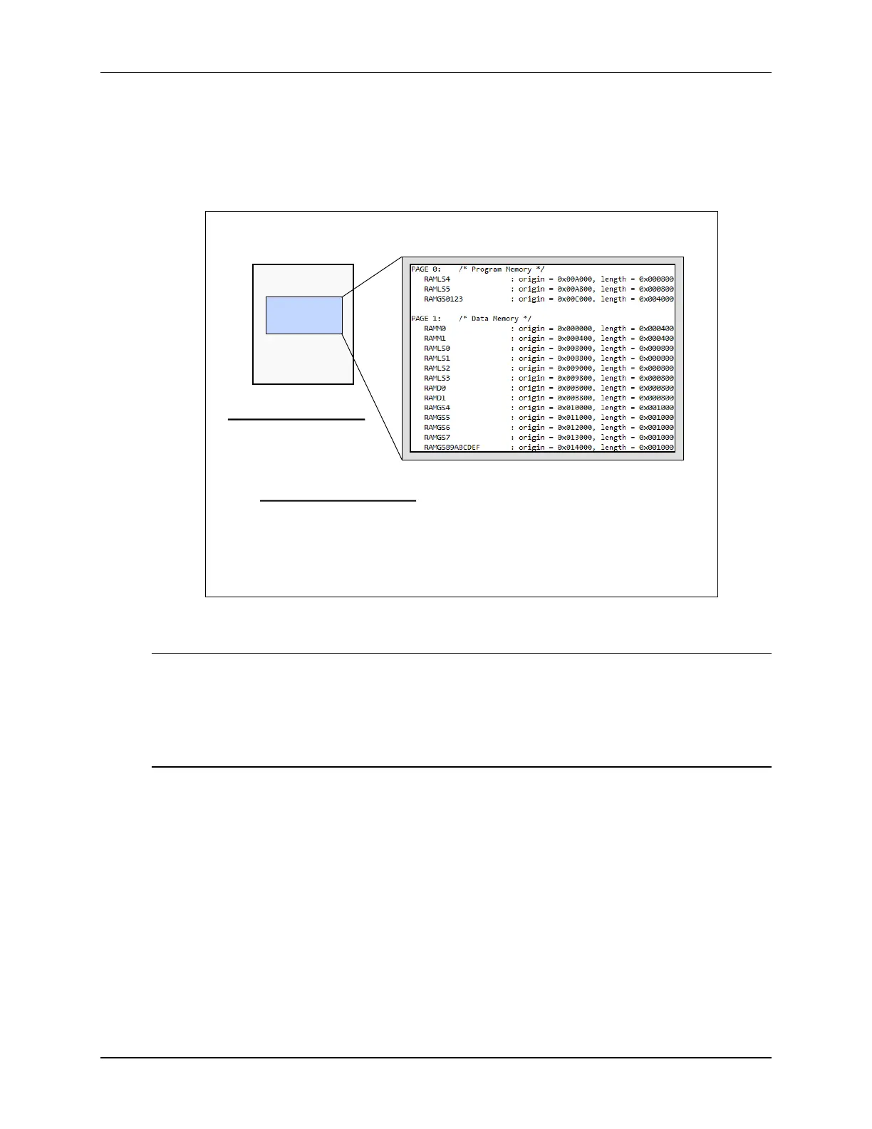
System Description:
• TMS320F2837x
• All internal RAM
blocks allocated
Placement of Sections:
• .text into RAM Block RAMGS0123 on PAGE 0 (program memory)
• .cinit into RAM Block RAMGS0123 on PAGE 0 (program memory)
• .ebss into RAM Block RAMM0 on PAGE 1 (data memory)
• .stack into RAM Block RAMM1 on PAGE 1 (data memory)
F2837x
Memory
on-chip
memory
Initial Hardware Set Up
Note: The lab exercises in this workshop have been developed and targeted for the F28379D
LaunchPad. Optionally, the F28379D Experimenter Kit can be used. Other F2807x or
F2837xS development tool kits may be used and might require some minor modifications
to the lab code and/or lab directions; however the Inter-Processor Communications lab
exercise will require either the F28379D LaunchPad or the F28379D Experimenter Kit.
Refer to Appendix A for additional information about the F28379D Experimenter Kit.
• F28379D LaunchPad:
Using the supplied USB cable – plug the USB Standard Type A connector into the computer USB
port and the USB Mini Type B connector into the LaunchPad. This will power the LaunchPad
using the power supplied by the computer USB port. Additionally, this USB port will provide the
JTAG communication link between the device and Code Composer Studio.
At the beginning of the workshop, boot mode switch S1 position 3 must be set to “1 – ON”. This
will configure the device for emulation boot mode.
Initial Software Set Up
Code Composer Studio must be installed in addition to the workshop files. A local copy of the
required C2000Ware files is included with the lab files. This provides portability, making the

 Loading...


