ePWM
TMS320F2837xD Microcontroller Workshop - Control Peripherals 7 - 5
ePWM
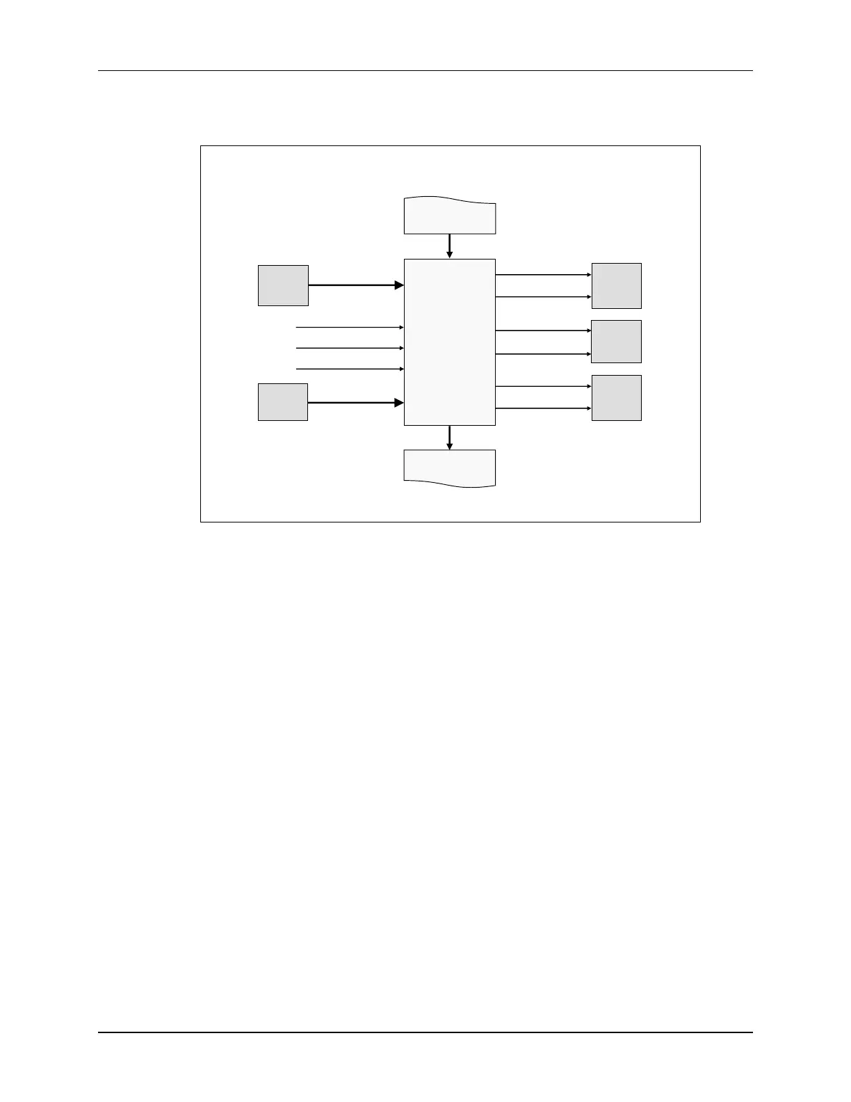
ePWM Module Signals and Connections
ePWMx
ePWMx
+1
EPWMxSYNCI
EPWMxSYNCO
PIE
CLA
EPWMxINT
EPWMxTZINT
ePWMx-1
EPWMxSOCB
EPWMxSOCA
ADC
ePWM
X-Bar
EMUSTOP – TZ6
CLOCKFAIL – TZ5
EQEPERR – TZ4
CPU
SYSCTRL
eQEP
EPWMxA
EPWMxB
GPIO
MUX
INPUT
X-Bar
Note: the order in which the ePWM modules are connected is determined by the device synchronization scheme
The ePWM modules are highly programmable, extremely flexible, and easy to use, while being
capable of generating complex pulse width waveforms with minimal CPU overhead or
intervention. Each ePWM module is identical with two PWM outputs, EPWMxA and EPWMxB,
and multiple modules can synchronized to operate together as required by the system application
design. The generated PWM waveforms are available as outputs on the GPIO pins. Additionally,
the EPWM module can generate ADC starter conversion signals and generate interrupts to the
PIE block. External trip zone signals can trip the output, as well as generate interrupts. The
outputs of the comparators are used as inputs to the ePWM X-Bar. Next, the internal details of
the ePWM module will be covered.

 Loading...


