Reset and Boot Process
TMS320F2837xD Microcontroller Workshop - Reset and Interrupts 4 - 7
process. This is the typical sequence followed during device power-up with the emulator con-
nected, allowing the user to control the boot process using the debugger.
Once the EMU_KEY bit fields are set to 0x5A, then the EMU_BMODE bit field values determines
the boot mode. The various Emulation Boot modes supported are Parallel I/O, SCI, SPI, I2C,
CAN, M0 RAM, FLASH, USB, and Wait. The GetMode and when EMU_BMODE bit fields have a
value of 0xFE or 0xFF are used to emulate the Stand-alone Boot mode.
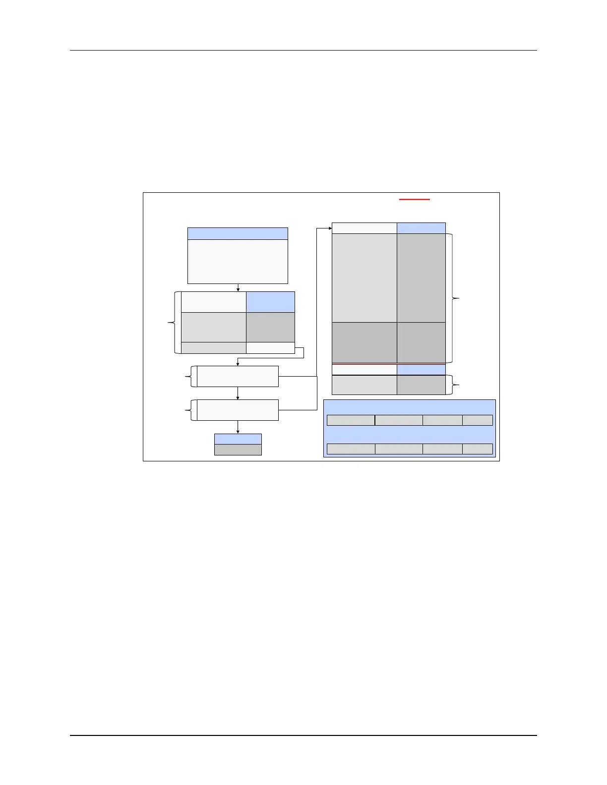
Stand-Alone Boot Mode
Stand-Alone Boot Mode
(TRST = 0)
Stand-Alone Boot
Boot determined by
2 GPIO pins and
Zx-BOOTCTRL :
OTP_KEY and OTP_BMODE
Emulator Not Connected
Boot Mode
Parallel I/O
SCI
Wait
GetMode
GPIO GPIO
72 84
0 0
0 1
1 0
1 1
Boot Mode
FLASH
NO
Boot Mode
Parallel I/O
SCI-A
SPI-A
I2C-A
CAN-A
M0 RAM
FLASH
USB-0
Wait
SCI-A *
SPI-A *
I2C-A *
CAN-A *
OTP_BMODE =
0x00
0x01
0x04
0x05
0x07
0x0A
0x0B
0x0C
other
0x81
0x84
0x85
0x87
Boot Mode
FLASH
Wait
OTP_BMODE =
0x0B
other
CPU1
GetMode
CPU2
GetMode
CPU1
only
Z1-BOOTCTRL
OTP_KEY = 0x5A ?
Z2-BOOTCTRL
OTP_KEY = 0x5A ?
NO
Use
Z1-
BOOTCTRL
YES
YES
Use
Z2-
BOOTCTRL
OTP_BOOTPIN1 OTP_BOOTPIN0 OTP_BMODE OTP_KEY
7 – 015 – 823 – 1631 – 24
CPU1 Zx-BOOTCTRL Register
reserved reserved OTP_BMODE OTP_KEY
7 – 015 – 823 – 1631 – 24
CPU2 Zx-BOOTCTRL Register
In Stand-alone boot mode, first GPIO pins 72 and 84 are checked to determine if the boot mode
is Parallel I/O, SCI, Wait, or GetMode. These pin can be remapped to any GPIO pins, if needed,
and the default “unconnected” pins set the boot mode to GetMode. In GetMode the OTP_KEY bit
fields in the Z1-BOOTCTRL and Z2-BOOTCTRL registers are checked for a value of 0x5A. An
un-programmed device will have these locations set as 1’s, and the flash boot mode is entered,
as expected for the default mode. If the OTP_KEY bit fields in either Z1-BOOTCTRL or Z2-
BOOTCTRL registers has a value of 0x5A, then the OTP_BMODE bit field values in the registers
determines the boot mode. The various Stand-alone Boot modes supported are Parallel I/O, SCI,
SPI, I2C, CAN, M0 RAM, FLASH, USB, and Wait.

 Loading...


