Oscillator/PLL Clock Module
TMS320F2837xD Microcontroller Workshop - System Initialization 5 - 5
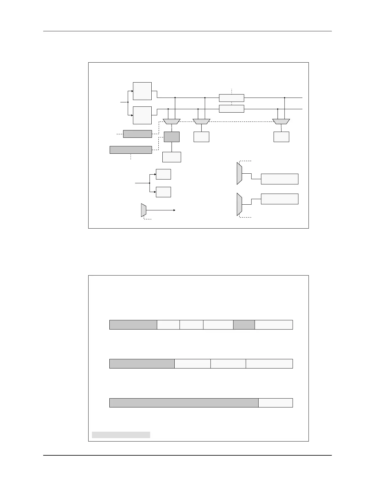
F2837xD Dual-Core System Clock
F2837xD Dual-Core System Clock
WDCLK
WD.2
WD.1
PLLSYSCLK
CPUSELy
CPU2.SYSCLK
CPU1.SYSCLK
PERx
PERx
CPU2
CPU1
LOSPCP
LOSPCP
CPU2.LSPCLK
CPU1.LSPCLK
PERCLKDIVSEL
/1, /2
EPWM
EPWMCLK
CPUTIMER2.2
CPUTIMER2.1
CPU1.SYSCLK
INTOSC1
INTOSC2
EXTCLK
AUXPLLCLK
CPU2.SYSCLK
INTOSC1
INTOSC2
EXTCLK
AUXPLLCLK
CPU2.TMR2CLKCTL
CPU1.TMR2CLKCTL
LSPCLKDIV
PERx
EPWMCLKDIV
PERx.SYSCLK PERx.LSPCLK
PERx.SYSCLK
EXTCLK
AUXCLKIN
CANxBCLKSEL
CANx Bit CLK
SCIx
SPIx
McBSPx
Peripherals
The PLL system clock is fed to both the CPU1 and CPU2 subsystems. By default, all peripherals
are assigned to the CPU1 subsystem. Using the CPU selection register, each individual
peripheral can be assigned to either the CPU1 or CPU2 subsystem. The clock for the EPWM
modules are limited to 100 MHz, and by using the peripheral clock divider selection register, this
clock can be divided down to meet this specification.
Clock Source Control Register
ClkCfgRegs.CLKSRCCTLx (lab file: SysCtrl.c)
0 = default
31 - 6 4 3 2 1 - 05
XTALOFF INTOSC2OFF reserved OSCCLKSRCSELWDHALTIreserved
31 - 6 3 - 2 1 - 05 - 4
CANBBCLKSEL CANABCLKSEL AUXOSCCLKSRCSELreserved
31 - 3 2 - 0
XCLKOUTSELreserved
XCLK Out Select
000 = PLLSYSCLK 100 = AUXCLK
001 = PLLCLK 101 = INTOSC1
010 = CPU1.SYSCLK 110 = INTOSC2
011 = CPU2.SYSCLK 111 = reserved
Oscillator Clock Source Select
00 = INTOSC2 10 = INTOSC1
01 = EXTCLK 11 = reserved
WD HALT Mode Ignore
0 = automatic turn on/off
1 = ignores HALT Mode
XTAL Oscillator Off
0 = on 1 = off
Internal OSC2 Off
0 = on 1 = off
CAN A/B Bit Clock Select
00 = PERx.SYSCLK 10 = AUXCLKIN
01 = EXTCLK 11 = reserved
AUX Osc. Clock Source Select
00 = INTOSC2 10 = AUXCLKIN
01 = EXTCLK 11 = reserved
x = 1
x = 2
x = 3
Note: register lock protected

 Loading...


