Analog-to-Digital Converter (ADC)
TMS320F2837xD Microcontroller Workshop - Analog Subsystem 6 - 5
ADC Block and Functional Diagrams
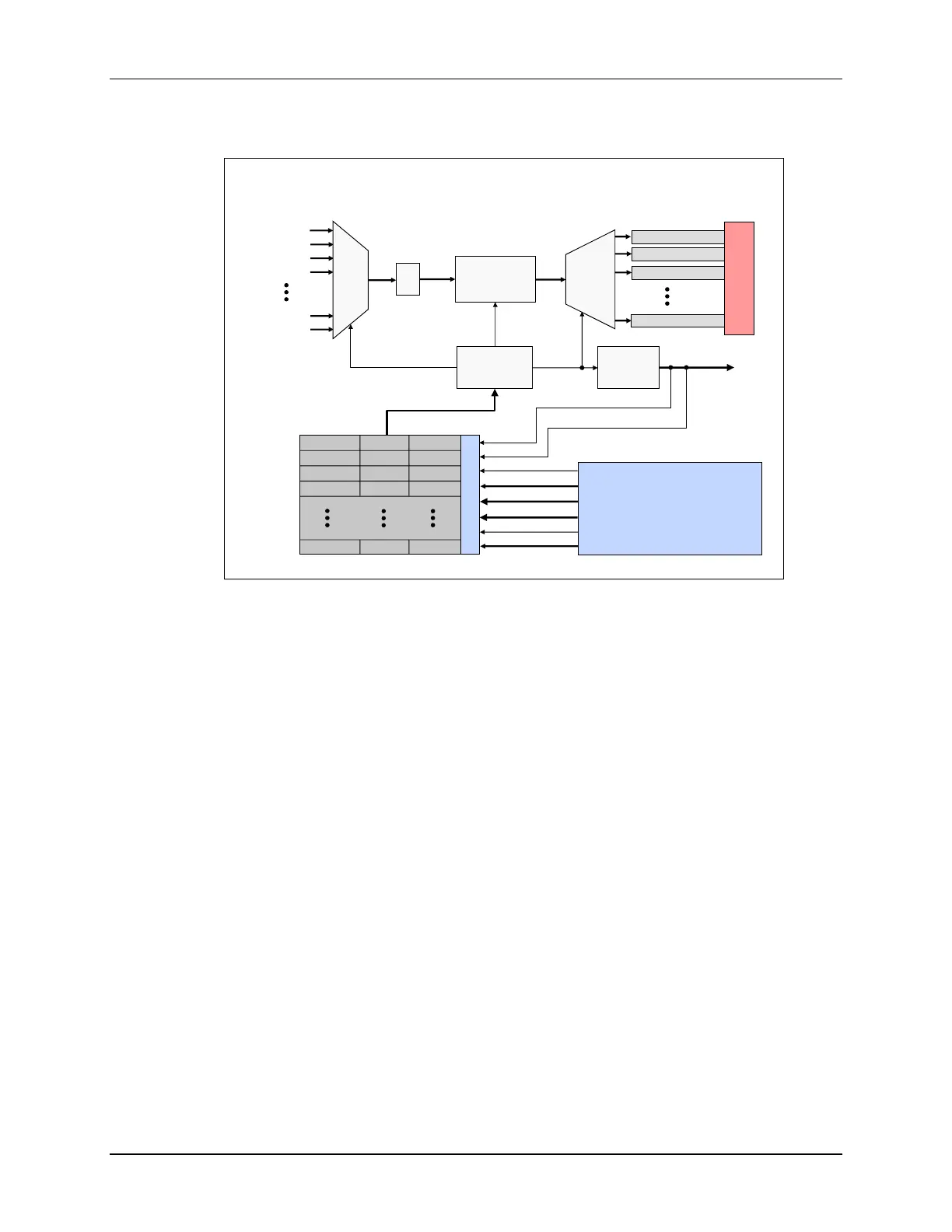
ADC Module Block Diagram
12/16-bit
A/D
Converter
SOCx
EOCx
S/H
MUX
ADCRESULT0
ADCRESULT1
ADCRESULT2
ADCRESULT15
Result
MUX
ADC
Generation
Logic
ADC full-scale
input range is
V
REFLO
to V
REFHI
CHSEL
ADC
Interrupt
Logic
ADCINT1-4
Software
External Pin
(GPIO/ADCEXTSOC)
EPWMxSOCA/C
(x = 1 to 12)
EPWMxSOCB/D
(x = 1 to 12)
CPU1 Timer
(0,1,2)
SOCx Signal
ADCINT1
ADCINT2
SOC0 TRIGSEL CHSEL ACQPS
SOC1 TRIGSEL CHSEL ACQPS
SOC2 TRIGSEL CHSEL ACQPS
SOC3 TRIGSEL CHSEL ACQPS
SOC15 TRIGSEL CHSEL ACQPS
SOCx Triggers
SOCx Configuration Registers
ADCIN1
ADCIN0
ADCIN2
ADCIN3
ADCIN14
ADCIN15
CPU2 Timer
(0,1,2)
Post Processing
Blocks
The ADC triggering and conversion sequencing is managed by a series of start-of-conversion
(SOCx) configuration registers. Each SOCx register configures a single channel conversion,
where the SOCx register specifies the trigger source that starts the conversion, the channel to
convert, and the acquisition sample window duration. Multiple SOCx registers can be configured
for the same trigger, channel, and/or acquisition window. Configuring multiple SOCx registers to
use the same trigger will cause that trigger to perform a sequence of conversions, and configuring
multiple SOCx registers for the same trigger and channel can be used to oversample the signal.
The various trigger sources that can be used to start an ADC conversion include the General-
Purpose Timers from each CPU subsystem, the ePWM modules, an external pin, and by
software. Also, the flag setting of either ADCINT1 or ADCINT2 can be configured as a trigger
source which can be used for continuous conversion operation. The ADC interrupt logic can
generate up to four interrupts. The results for SOC 0 through 15 appear in result registers 0
through 15, respectively.

 Loading...


