Analog-to-Digital Converter (ADC)
6 - 20 TMS320F2837xD Microcontroller Workshop - Analog Subsystem
ADC Calibration and Reference
Built-In ADC Calibration
TI reserved OTP contains device specific calibration
data for the ADC, internal oscillators and buffered DAC
The Boot ROM contains a Device_cal() routine that
copies the calibration data to their respective registers
Device_cal() must be run to meet the specifications in
the datasheet
The Bootloader automatically calls Device_cal() such that no
action is normally required by the user
If the Bootloader is bypassed (e.g. during development)
Device_cal() should be called by the application:
AdcSetMode() function is called in the source code to
trim the ADC
#define Device_cal (void (*)(void))0x70282
void main(void)
{
(*Device_cal)(); // call Device_cal()
}
Manual ADC Calibration
If the offset and gain errors in the datasheet are unacceptable for
your application, or you want to also compensate for board level
errors (e.g. sensor or amplifier offset), you can manually calibrate
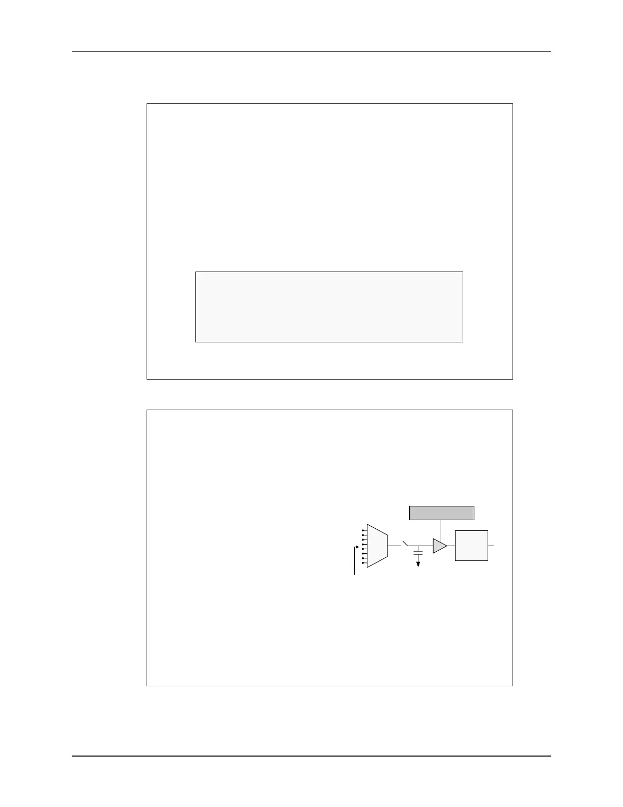
Offset error (12-bit mode)
Compensated in analog with
the ADCOFFTRIM register
No reduction in full-scale range
Configure input to VREFLO,
set ADCOFFTRIM to maximum
offset error, and take a reading
Re-adjust ADCOFFTRIM to
make result zero
Gain error
Compensated in software
Some loss in full-scale range
Requires use of a second ADC input pin and an upper-range reference
voltage on that pin; see “TMS320x280x and TMS320x2801x ADC
Calibration” appnote #SPRAAD8A for more information
C
H
VREFLO
ADCOFFTRIM
ADC

 Loading...


