Analog-to-Digital Converter (ADC)
6 - 12 TMS320F2837xD Microcontroller Workshop - Analog Subsystem
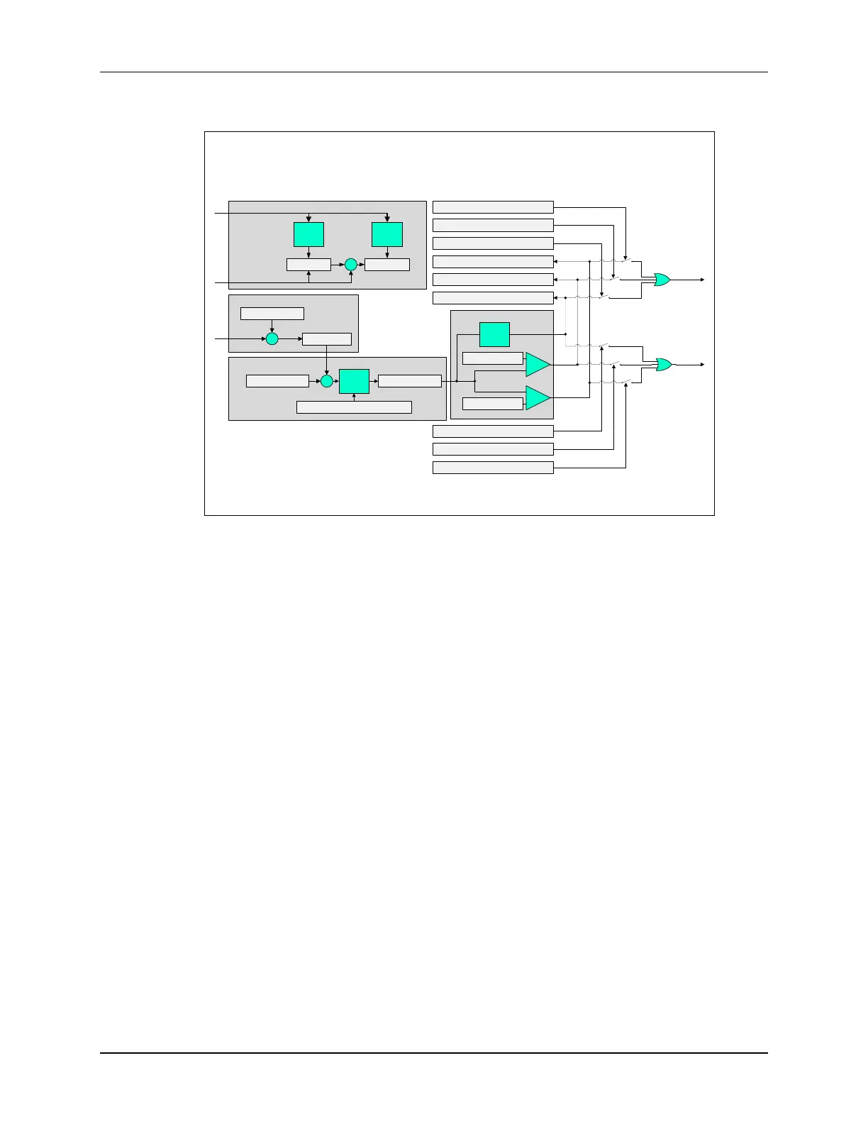
Post Processing Block - Diagram
Delay Capture
latch
Threshold Compare
Error/Bipolar Calculation
Offset Correction
w/ Saturation
ADCPPBxTRIPHI
ADCPPBxTRIPLO
Σ
ADC Output
ADCPPBxOFFCAL
ADCRESULTy
ADCPPBxOFFREF
saturate
Σ
ADCPPBxRESULT
EVENTx
-
+
-
+
Twos
Comp
Inv
Enable
INTx
ADCEVTSTAT.PPBxZERO
Zero
Crossing
Detect
ADCPPBxCONFIG.TWOSCOMPEN
ADCEVTSTAT.PPBxTRIPHI
ADCEVTSTAT.PPBxTRIPLO
ADCEVTSEL.PPBxZERO
ADCEVTSEL.PPBxTRIPHI
ADCEVTSEL.PPBxTRIPLO
ADCEVTINTSEL.PPBxZERO
ADCEVTINTSEL.PPBxTRIPLO
ADCEVTINTSEL.PPBxTRIPHI
FREECOUNT
REQSTAMPx
DLYSTAMPx
SOC
Trigger
Detect
SOC
Start
Detect
SOC Control Signals
Σ
-
+
latch
+
-
+
To further enhance the capabilities of the ADC, each ADC module incorporates four post-
processing blocks (PPB), and each PPB can be linked to any of the ADC result registers. The
PPBs can be used for offset correction, calculating an error from a set-point, detecting a limit and
zero-crossing, and capturing a trigger-to-sample delay. Offset correction can simultaneously
remove an offset associated with an ADCIN channel that was possibly caused by external
sensors or signal sources with zero-overhead, thereby saving processor cycles. Error calculation
can automatically subtract out a computed error from a set-point or expected result register value,
reducing the sample to output latency and software overhead. Limit and zero-crossing detection
automatically performs a check against a high/low limit or zero-crossing and can generate a trip
to the ePWM and/or generate an interrupt. This lowers the sample to ePWM latency and reduces
software overhead. Also, it can trip the ePWM based on an out-of-range ADC conversion without
any CPU intervention which is useful for safety conscious applications. Sample delay capture
records the delay between when the SOCx is triggered and when it begins to be sampled. This
can enable software techniques to be used for reducing the delay error.

 Loading...


