ADC Control Register 1
AdczRegs.ADCCTL1 (z = a, b, c, or d)
ADCBSY ADCBSYCHNreserved
11 - 8
15 - 14
13 12
ADC Busy
0 = ADC available
1 = ADC busy
ADC Busy Channel
When ADCBSY =
0: last channel converted
1: channel currently processing
00h = ADCIN0 08h = ADCIN9
01h = ADCIN1 09h = ADCIN10
02h = ADCIN2 0Ah = ADCIN11
03h = ADCIN3 0Bh = ADCIN12
04h = ADCIN4 0Ch = ADCIN13
05h = ADCIN5 0Dh = ADCIN14
06h = ADCIN6 0Eh = ADCIN15
07h = ADCIN7 0Fh = ADCIN16
reserved
ADCPWDNZ reserved reservedINTPULSEPOS
1 - 026 - 37
ADC Power Down
Analog circuitry is:
0 = powered down
1 = powered up
INT Pulse
Generation Control
0 = beginning of
conversion
1 = one cycle prior
to result
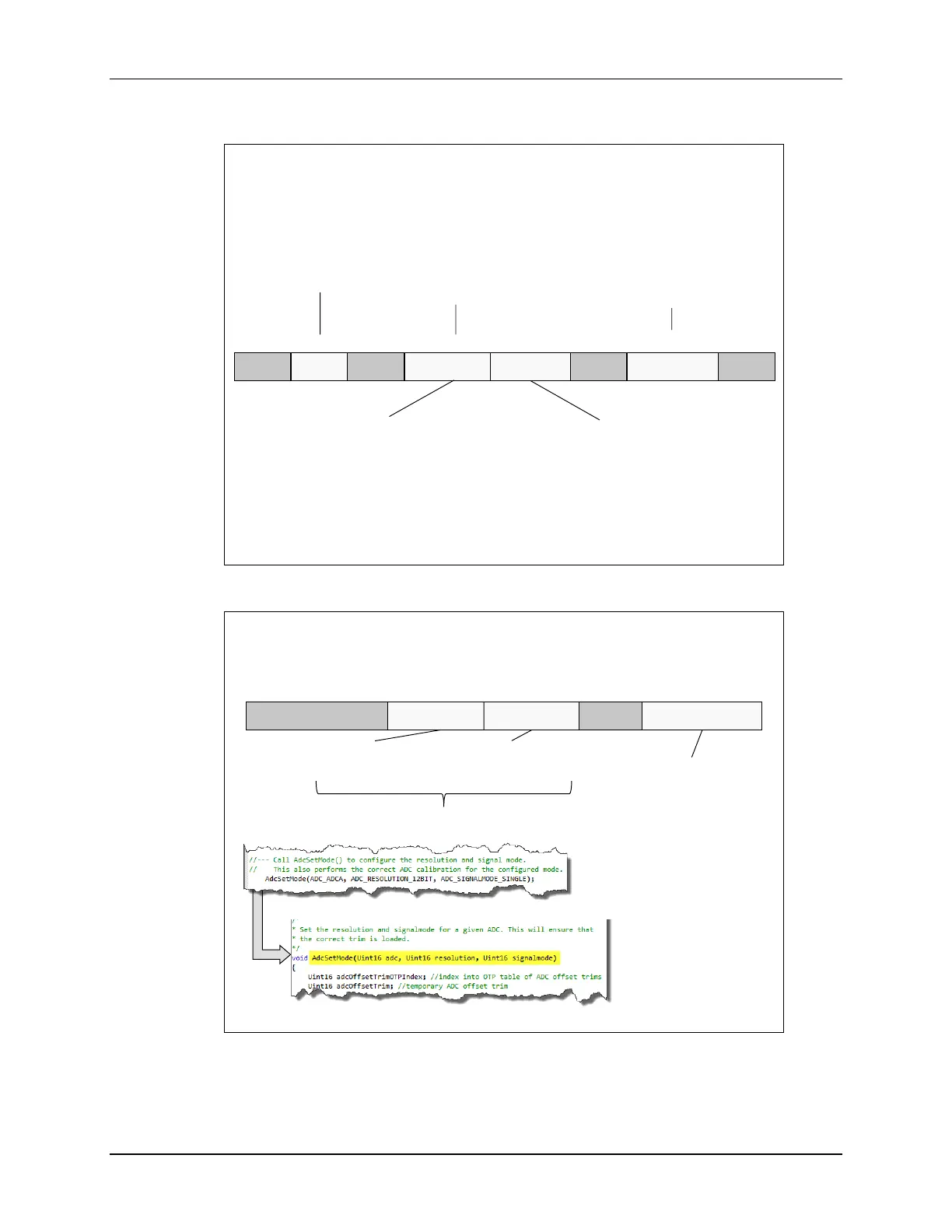
ADC Control Register 2
AdczRegs.ADCCTL2 (z = a, b, c, or d)
SIGNALMODE RESOLUTION
reserved
15 - 8 7 6 5 - 4 3 - 0
PRESCALE
reserved
0000 = Input Clock / 1.0
0001 = Invalid
0010 = Input Clock / 2.0
0011 = Input Clock / 2.5
0100 = Input Clock / 3.0
0101 = Input Clock / 3.5
0110 = Input Clock / 4.0
1000 = Input Clock / 4.5
1001 = Input Clock / 5.0
1010 = Input Clock / 5.5
1011 = Input Clock / 6.0
1100 = Input Clock / 6.5
1101 = Input Clock / 7.0
1110 = Input Clock / 7.5
1111 = Input Clock / 8.0
ADC Clock Prescale
ADCCLK equals:
ADC Resolution
0 = 12-bit resolution
1 = 16-bit resolution
Signaling Mode
0 = single-ended
1 = differential
Configured by AdcSetMode() function in source code
Adc.c
F2837xD_Adc.c
Definitions for selecting ADC signaling mode and resolution defined in F2837xD_Adc_defines.h

 Loading...


