Lab 6: Analog-to-Digital Converter
TMS320F2837xD Microcontroller Workshop - Analog Subsystem 6 - 35
28. Run the code (real-time mode) using the Script function: Scripts Realtime
Emulation Control Run_Realtime_with_Reset
29. At this point, the graph should be displaying a DC signal near zero. Click on the
dacOffset variable in the Expressions window and change the value to 800. This
changes the DC output of the DAC which is applied to the ADC input. The level of the
graph display should be about 800 and this should be reflected in the value shown in the
memory buffer (note: 800 decimal = 0x320 hex).
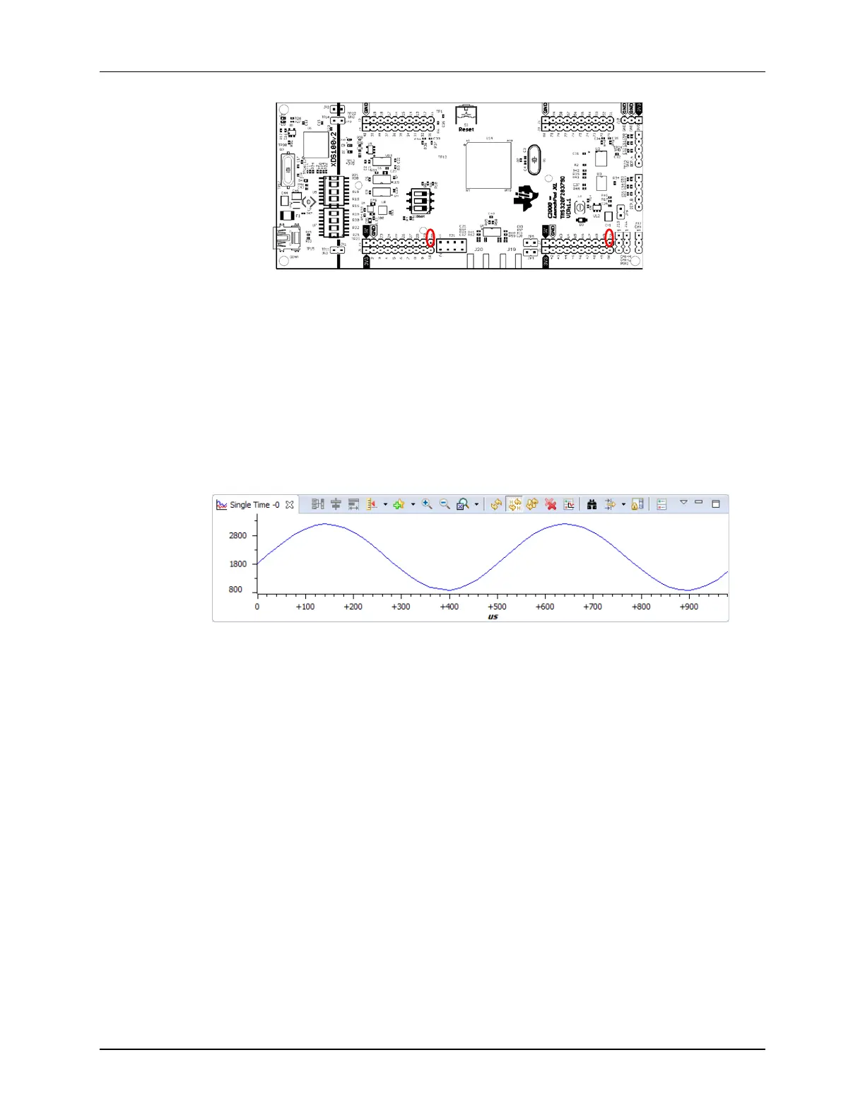
30. Enable the sine generator by changing the variable Sine_Enable in the Expressions
window to 1.
31. You should now see sinusoidal data in the graph window.
32. Try removing and re-connecting the jumper wire to show this is real data is running in
real-time emulation mode. Also, you can try changing the DC offset variable to move the
input waveform to a different average value (the maximum distortion free offset is about
2000).
33. Fully halt the code (real-time mode) by using the Script function: Scripts
Realtime Emulation Control Full_Halt
Terminate Debug Session and Close Project
34. Terminate the active debug session using the Terminate button. This will close the
debugger and return Code Composer Studio to the CCS Edit perspective view.
35. Next, close the project by right-clicking on Lab6 in the Project Explorer window and
select Close Project.
Optional Exercise
If you finish early, you might want to experiment with the code by observing the effects of
changing the OFFTRIM value. Open a watch window to the AdcaRegs.ADCOFFTRIM register
and change the OFFTRIM value. If you did not get 0x0000 in step 11, you can calibrate out the
offset of your device. If you did get 0x0000, you can determine if you actually had zero offset, or

 Loading...


