ePWM
7 - 18 TMS320F2837xD Microcontroller Workshop - Control Peripherals
And finally in the example above, again using different output actions on the up-count and down-
count, the EPWMA output is being set high on the compare A up-count match and being cleared
low on the compare B down-count match. The EPWMB output is being cleared low on the zero
match and being set high on the period match.
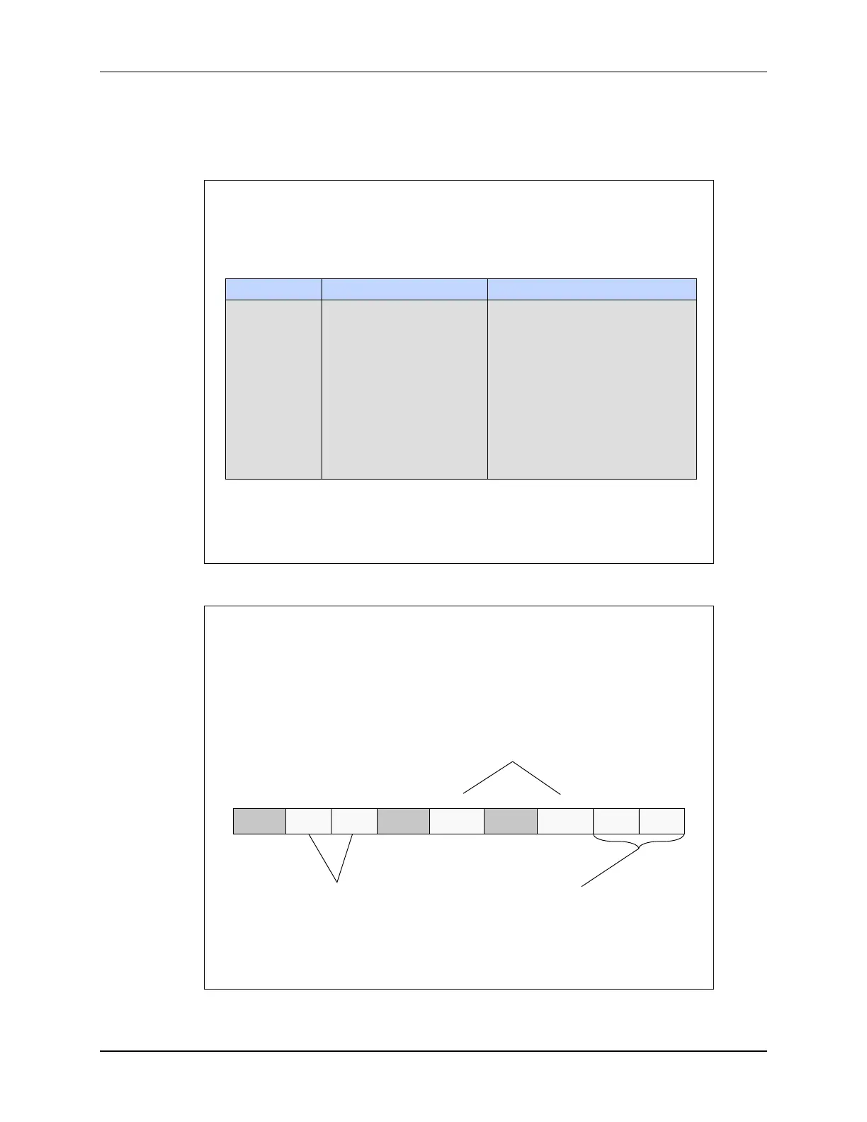
Name Description Structure
AQCTL AQ Control Register EPwmxRegs.AQCTL.all =
AQCTLA AQ Control Output A EPwmxRegs.AQCTLA.all =
AQCTLA2 AQ Control Output A EPwmxRegs.AQCTLA2.all =
AQCTLB AQ Control Output B EPwmxRegs.AQCTLB.all =
AQCTLB2 AQ Control Output B EPwmxRegs.AQCTLB2.all =
AQTSRCSEL AQ T Source Select EPwmxRegs.AQTSRCSEL =
AQSFRC AQ S/W Force EPwmxRegs.AQSFRC.all =
AQCSFRC AQ Cont. S/W Force EPwmxRegs.AQCSFRC.all =
ePWM Action Qualifier Sub-Module
Registers
(lab file: EPwm.c)
ePWM Action Qualifier Control Register
EPwmxRegs.CTL
4
reserved
9 - 8
LDAQB
MODE
LDAQB
SYNC
LDAQA
SYNC
LDAQA
MODE
SHDWAQ
AMODE
reserved
6
SHDQAQ
BMODE
reserved
1 - 03 - 257
11 - 1015 - 12
Action Qualifier A / Action Qualifier B
Operating Mode
0 = shadow mode;
double buffer w/ shadow register
1 = immediate mode;
shadow register not used
Action Qualifier A / Action Qualifier B
Shadow Load Mode
00 = load on CTR = 0
01 = load on CTR = PRD
10 = load on CTR = 0 or PRD
11 = freeze (no load possible)
Action Qualifier A / Action Qualifier B
Shadow to Active Load on SYNC event
00 = only on LDAQxMODE
01 = on both LDAQxMODE and SYNC
10 = only when SYNC is received
11 = reserved

 Loading...


