eQEP
7 - 48 TMS320F2837xD Microcontroller Workshop - Control Peripherals
A quadrature decoder state machine is used to determine position from two quadrature signals.
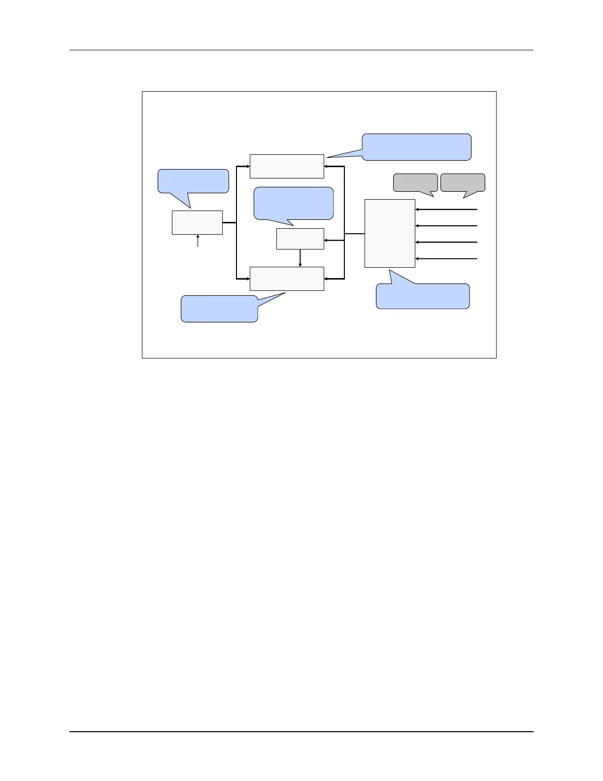
eQEP Module Block Diagram
Quadrature
Decoder
EQEPxA/XCLK
EQEPxB/XDIR
EQEPxI
EQEPxS
Position/Counter
Compare
Quadrature
Capture
32-Bit Unit
Time-Base
QEP
Watchdog
Generate the direction and
clock for the position counter
in quadrature count mode
Generate a sync output
and/or interrupt on a
position compare match
Measure the elapsed time
between the unit position events;
used for low speed measurement
Generate periodic
interrupts for velocity
calculations
Monitors the quadrature
clock to indicate proper
operation of the motion
control system
Quadrature -
clock mode
Direction -
count mode
CPUx.SYSCLK
The inputs include two pins (QEPA and QEPB) for quadrature-clock mode or direction-count
mode, an index pin (QEPI), and a strobe pin (QEPS). These pins are configured using the GPIO
multiplexer and need to be enabled for synchronous input. In quadrature-clock mode, two square
wave signals from a position encoder are inputs to QEPA and QEPB which are 90 electrical
degrees out of phase. This phase relationship is used to determine the direction of rotation. If
the position encoder provides direction and clock outputs, instead of quadrature outputs, then
direction-count mode can be used. QEPA input will provide the clock signal and QEPB input will
have the direction information. The QEPI index signal occurs once per revolution and can be
used to indicate an absolute start position from which position information is incrementally
encoded using quadrature pulses. The QEPS strobe signal can be connected to a sensor or limit
switch to indicate that a defined position has been reached.

 Loading...


