Lab 7: Control Peripherals
7 - 54 TMS320F2837xD Microcontroller Workshop - Control Peripherals
This information will be used in the next step.
20. Modify the end of ECap.c to do the following:
- Enable the “ECAP1” interrupt in the PIE (Hint: use the PieCtrlRegs structure)
- Enable the appropriate core interrupt in the IER register
Build and Load
21. Save all changes to the files and build the project by clicking Project Build
Project, or by clicking on the “Build” button if you have added it to the tool bar. Select
Yes to “Reload the program automatically”.
Run the Code – Pulse Width Measurement
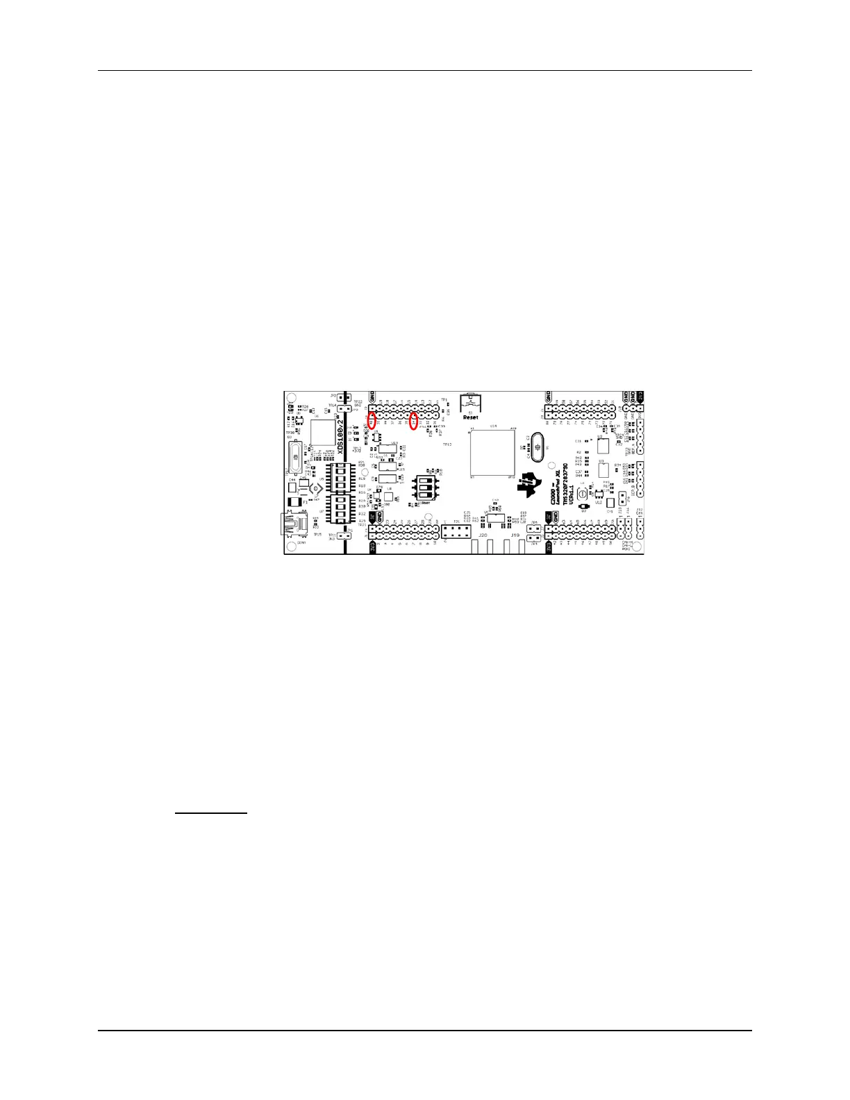
22. Using a jumper wire, connect the PWM1A (header J4, pin #40) to ECAP1 (header J4, pin
#34, feed from the Input X-bar using GPIO24) on the LaunchPad
. Refer to the
following diagram for the pins that need to be connected.
23. Open a memory browser to view the address label PwmPeriod. (Type &PwmPeriod in
the address box). The address label PwmDuty (address &PwmDuty) should appear in
the same memory browser window. Scroll the window up, if needed.
24. Set the memory browser properties format to “32-Bit UnSigned Int”. We will be running
our code in real-time mode, and we will need to have the memory browser continuously
refresh.
25. Run the code (real-time mode) by using the Script function: Scripts Realtime
Emulation Control Run_Realtime_with_Reset. Notice the values for
PwmDuty and PwmPeriod.
26. Fully halt the CPU (real-time mode) by using the Script function: Scripts
Realtime Emulation Control Full_Halt.
Questions:
• How do the captured values for PwmDuty and PwmPeriod relate to the compare register
CMPA and time-base period TBPRD settings for ePWM1A?
• What is the value of PwmDuty in memory?
• What is the value of PwmPeriod in memory?
• How does it compare with the expected value?

 Loading...


