Serial Communications Interface (SCI)
TMS320F2837xD Microcontroller Workshop - Communications 12 - 9
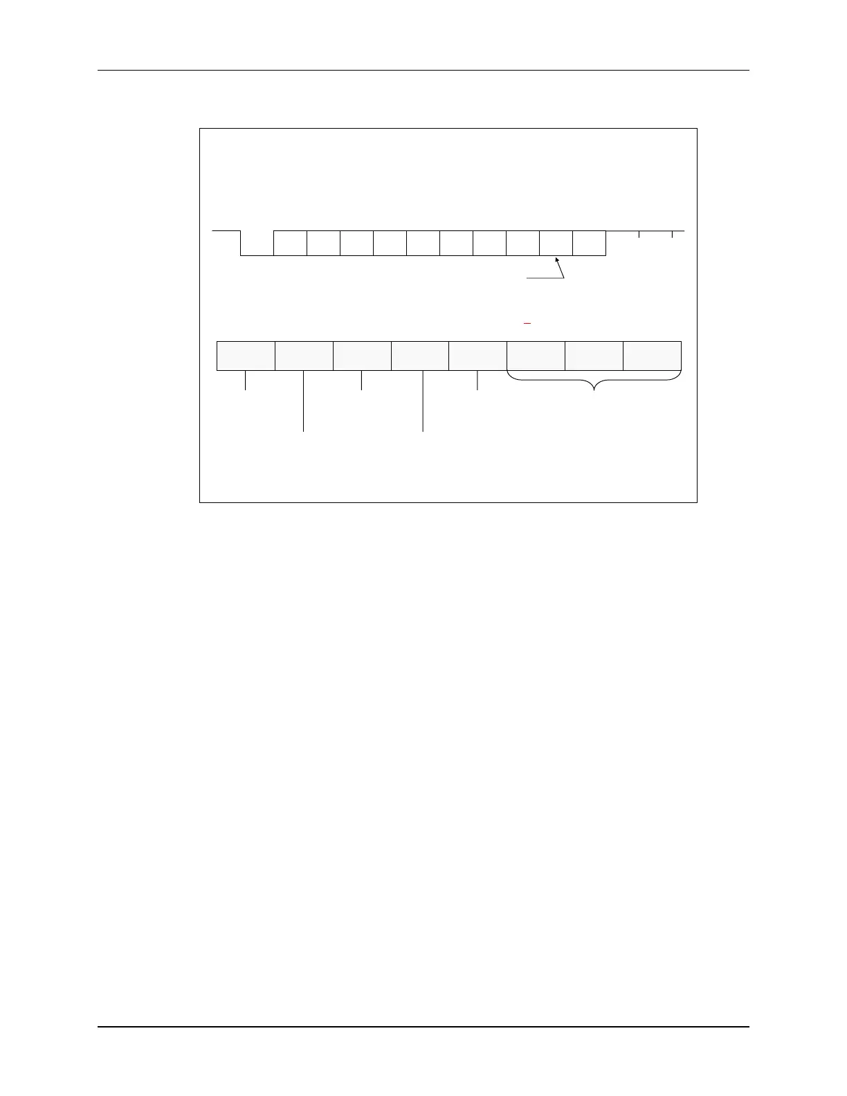
SCI Data Format
This bit present only in Address-bit mode
NRZ (non-return to zero) format
Communications Control Register (ScixRegs.SCICCR)
0 = 1 Stop bit
1 = 2 Stop bits
0 = Odd
1 = Even
0 = Disabled
1 = Enabled
0 = Disabled
1 = Enabled
0 = Idle-line mode
1 = Addr-bit mode
# of data bits = (binary + 1)
e.g. 110b gives 7 data bits
Stop
Bits
Even/Odd
Parity
Parity
Enable
Loopback
Enable
Addr/Idle
Mode
SCI
Char2
SCI
Char1
SCI
Char0
7 6 5 4 3 2 1 0
Start
LSB
2
3 4 5 6 7 MSB
Addr/
Data
Parity
Stop 1 Stop 2
The basic unit of data is called a character and is 1 to 8 bits in length. Each character of data is
formatted with a start bit, 1 or 2 stop bits, an optional parity bit, and an optional address/data bit.
A character of data along with its formatting bits is called a frame. Frames are organized into
groups called blocks. If more than two serial ports exist on the SCI bus, a block of data will
usually begin with an address frame which specifies the destination port of the data as
determined by the user’s protocol.
The start bit is a low bit at the beginning of each frame which marks the beginning of a frame.
The SCI uses a NRZ (Non-Return-to-Zero) format which means that in an inactive state the
SCIRX and SCITX lines will be held high. Peripherals are expected to pull the SCIRX and SCITX
lines to a high level when they are not receiving or transmitting on their respective lines.
When configuring the SCICCR, the SCI port should first be held in an inactive state. This is
done using the SW RESET bit of the SCI Control Register 1 (SCICTL1.5). Writing a 0 to this bit
initializes and holds the SCI state machines and operating flags at their reset condition. The
SCICCR can then be configured. Afterwards, re-enable the SCI port by writing a 1 to the SW
RESET bit. At system reset, the SW RESET bit equals 0.

 Loading...


