ELECTRICAL
4262930-Rev A 4-69
4
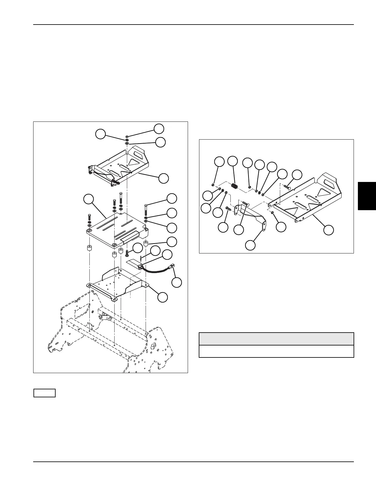
Battery Tray and Power Module
Mount
Removal
See Figure 4-69.
1. Park the mower safely. (See “Park Mower Safely” on
page 1-5.)
2. Remove battery pack. (See “Battery Pack” on
page 4-56.)
Figure 4-69
NOTE
3. Label all wires before disconnecting to ensure
correct installation.
4. Disconnect harness connector (12).
5. Loosen the three nuts (2) and slide battery tray (4) to
gain access to the four screws (5).
6. Remove four screws (5), lock washers (6), flat
washers (7), power module mount (14), spacers (8),
and power module mounting plate (13).
7. Remove two rivets (10) and remove ceramic resistor
(11) from power module mounting plate (13).
8. Remove three nuts (2), lock washers (1), flat
washers (3), and carriage bolts (9).
9. Remove battery tray (4) from power module mount
(14).
Disassembly and Assembly
See Figure 4-70.
Figure 4-70
Assembly Note
Inspect extension springs for wear prior to assembly.
Installation
Installation Notes
• Install battery tray and power module mount by
reversing the order of removal.
• Apply dielectric grease (Jacobsen PN 365422) to any
connectors removed.
2
1
5
4
TN4442
3
6
7
14
8
13
10
11
12
9
1 Lock Nut (6) 5 Carriage Bolt (4)
2 Extension Spring (2) 6 Battery Tray
3Nut (8) 7Clip
4 Lock Washer (4) 8 Screw (2)
Required Materials
Dielectric Grease (Jacobsen PN 365422)
TN4441
4
3
1
6
8
3
2
4
3
3
1
5
7
1
5