8-24 4262930-Rev A
CUTTING UNIT
8
Bedknife
Removal and Installation
NOTE
This procedure is intended for use with machines
equipped with standard fastener type bedknives. For
machines equipped with an optional MAGKnife™
bedknife system, adjustments are similar, but the
bedknife is secured to the bedknife backing by a series of
magnets and aligned by dowel pins rather than being
secured by screws.
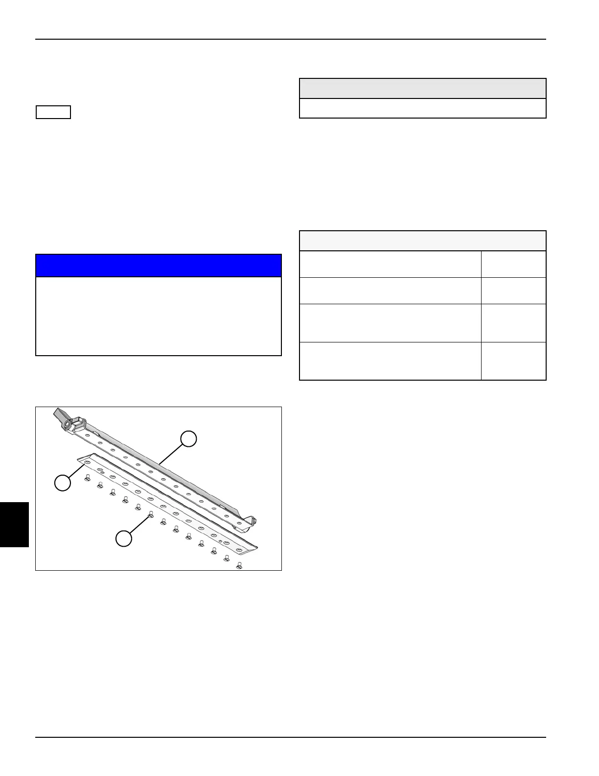
See Figure 8-32.
1. Park the mower safely. (See “Park Mower Safely” on
page 1-5.)
NOTICE
2. Remove bedknife backing assembly. (See “Bedknife
Backing Assembly” on page 8-22.)
Figure 8-32
3. Remove thirteen screws (2) and bedknife (3) from
the bedknife backing (1).
Installation Notes
• Install bedknife by reversing the order of removal.
• Apply anti-seize compound to screws (2).
• Tighten screws (2) to 90–120 lb-in. (10.2–13.6 N·m),
starting with screws in the center and working out to
the ends of the bedknife.
• Grind bedknife after assembling to bedknife backing
as specified below for the specific bedknife installed:
• Adjust bedknife-to-reel gap.
(See “Bedknife-to-Reel Adjustment” on page 8-14.)
Gen-Set Models: Before tipping mower back for
service, the fuel lever must be moved to the OFF
position to prevent fuel from leaking into the
crankcase. Do not leave the mower tipped back
for an extended length of time or oil may migrate
into the combustion chamber.
TN2635
1
2
3
Required Materials
Anti-Seize Compound
Bedknife Specifications
Bedknife Front Face Height
(minimum)
in. (mm) 0.035 (0.9)
Bedknife Front Face Angle
(all bedknives)
degrees 5
Bedknife Top Face Angle
(rear relief) (all bedknives
except Super Tournament)
degrees 8–10
Super Tournament Bedknife
Top Face Angle
(rear relief)
degrees 5–7