5-16 4262930-Rev A
POWER TRAIN
5
Figure 5-39
7. Install the seal cover (11).
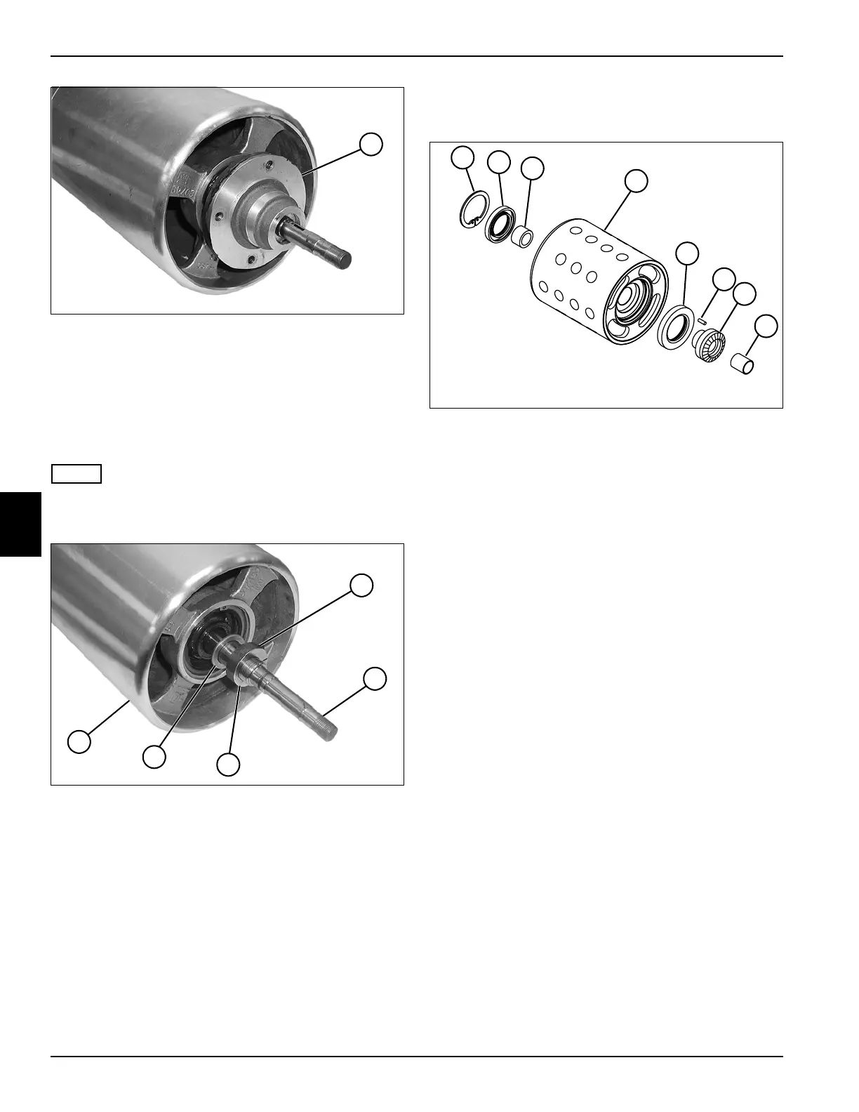
Traction Drum Assembly
Removal and Installation
See Figure 5-40.
NOTE
The right and left traction drum assemblies are removed
and installed the same way. Right drum shown.
Figure 5-40
1. Loosen the screw (1) and remove locking collar (3)
from the traction drum shaft (2).
2. Remove washer (4).
3. Remove drum assembly (5) from traction drum shaft
(2).
Installation Notes
• Install traction drum by reversing the order of
removal.
• Tighten non-pulley side nut until it just contacts
bearing.
• Tighten pulley nut to 30–35 lb-ft (40.6–47.4 N·m).
Disassembly and Assembly
See Figure 5-41.
Figure 5-41
1. Remove retaining ring (1), grease seal (2), and
bushing (3) from roller (4).
2. Remove differential gear (7) from roller (4).
3. Inspect bushing (8). Replace as needed.
4. Remove grease seal (5).
Assembly Notes
• Assembly is done by reversing the order of
disassembly.
• Install new grease seals (2 and 5).
• Apply grease that meets or exceeds NLGI Grade 2
LB specifications to the differential gear teeth (7) and
bushings (3 and 8) before assembly.
11
TN0241
1
TN0245
2
3
4
5
1 Retaining Ring 5 Grease Seal
2 Grease Seal 6 Pin (Press Fit)
3 Bushing (Press Fit) 7 Differential Gear
4 Roller 8 Bushing (Press Fit)
TN0246
1
2
3
4
5
8
7
6