ELECTRICAL
4262930-Rev A 4-65
4
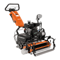
Figure 4-60
6. Install traction motor and mount assembly (20) and
transfer belt (11), using screw (16), flat washer (17),
lock washer (18), and nut (19). Do not tighten at this
time.
7. Install two screws (12), flat washers (13), lock
washers (14), and nuts (15).
8. Adjust transfer belt tension. (See “Traction Drive Belt
Tension Check and Adjustment” on page 5-5.)
Figure 4-61
9. Install new cable tie (22).
NOTE
Do NOT apply dielectric grease or any lubricant to
traction motor harness connectors.
10. Connect traction motor harness connectors (21).
11. Tighten all hardware.
12. Install traction drive belt cover. (See “Traction Drive
Belt Cover” on page 5-7.)
13. For battery pack powered mowers, install power
module. (See “Battery Tray and Power Module
Mount” on page 4-69.)
14. For gen-set powered mowers, install engine. (See
“Engine” on page 3-4.)
Throttle Potentiometer
Removal and Installation
See Figure 4-62.
1. Park the mower safely. (See “Park Mower Safely” on
page 1-5.)
2. Remove handle cover. (See “Handle Cover” on
page 6-4.)
3. Remove handle and Operator Presence Control
(OPC) bail. (See “Handle and OPC Bail” on
page 6-8.)
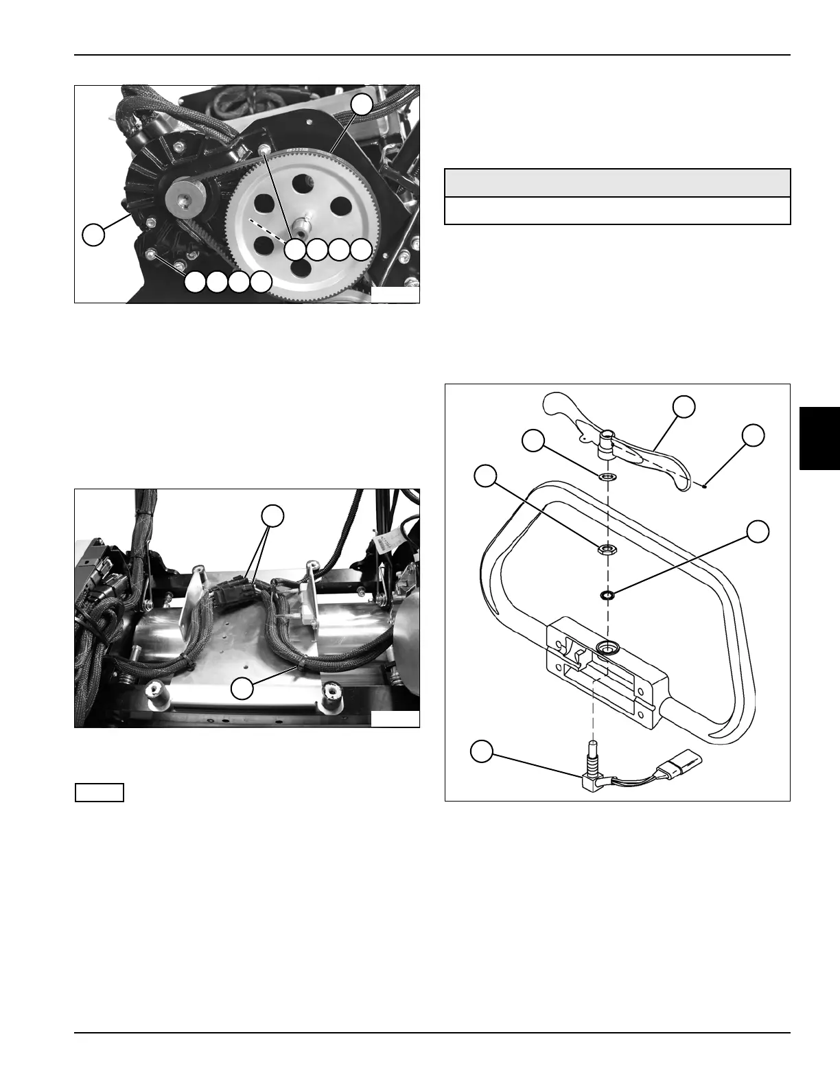
Figure 4-62
4. Loosen set screw (4). Remove speed paddle (3) and
spring washer (2).
5. Remove jam nut (1), star washer (5), and
potentiometer (6).
Installation Notes
• Install potentiometer by reversing the order of
removal.
• Apply dielectric grease (Jacobsen PN 365422) to any
connectors removed.
TN4636
11
20
12 13 14 15
16 17 18 19
TN4630
21
22
Required Materials
Dielectric Grease (Jacobsen PN 365422)
TN0619
1
2
3
4
6
5