SPECIFICATIONS AND GENERAL INFORMATION
4262930-Rev A 2-5
2
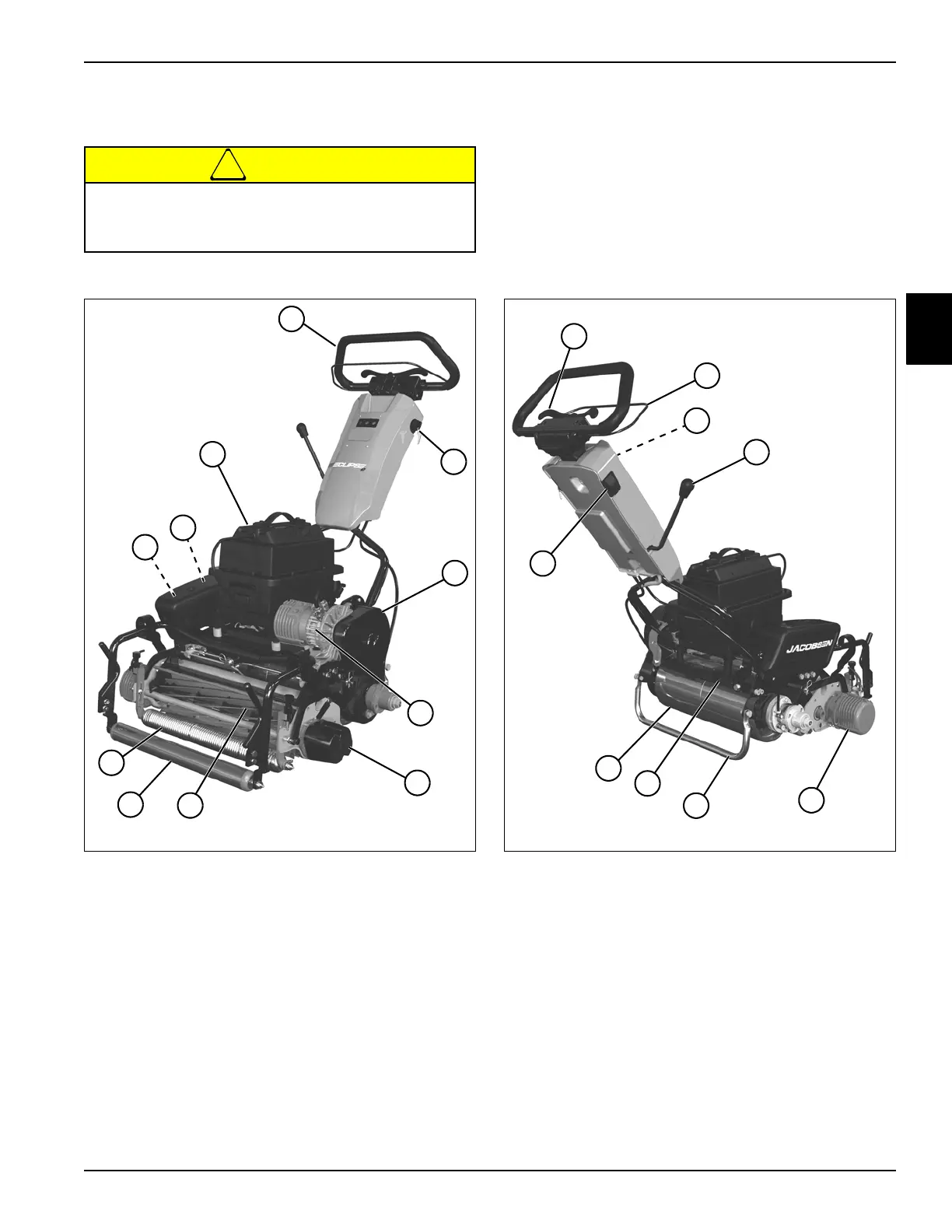
Battery Pack Models
See Figures 2-5 and 2-6.
!
CAUTION
Figure 2-5: Component Location—Front
Figure 2-6: Component Location—Rear
Become familiar with operator controls, machine
components, and correct operating procedures
before beginning repair procedures.
1 Operator Handle 7 Floating Head Frame
Roller
2 Key Switch 8 Front Roller
3 Belt Cover 9 Traction Motor Controller
4 Traction Motor 10 Reel Motor Controller
5 Reel Counterweight 11 Battery Pack
6Reel
TN4453
11
1
2
3
4
5
7
8
6
10
9
1 Speed Control Paddle 6 Kickstand
2 Operator Presence Control
(OPC) Bail
7 Product Identification Plate
3 LCD Controls and Display 8 Traction Drum
4 Park Brake Lever 9 Mow Switch
5Reel Motor
TN4454
2
9
1
6
8
5
7
4
3