ELECTRICAL
4262930-Rev A 4-51
4
Ceramic Resistor Test
See Figure 4-31.
1. Park the mower safely. (See “Park Mower Safely” on
page 1-5.)
Figure 4-31
NOTE
Label all wires before disconnecting to ensure correct
installation.
2. Disconnect ceramic resistor connector (1).
3. Measure the resistance between terminals
(2 and 3).
Is the resistance value 5 ohms ± 5% at 68° F?
YES Ceramic resistor is good.
NO Ceramic resistor is faulty; replace the
ceramic resistor.
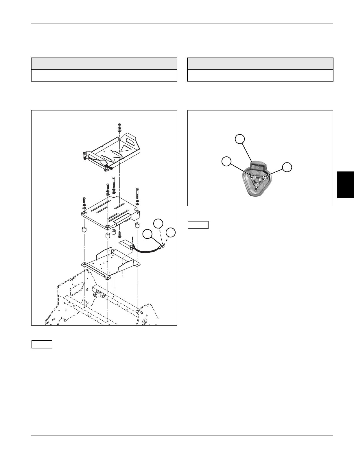
120-Ohm Resistor Connector Test
See Figure 4-32.
1. Park the mower safely. (See “Park Mower Safely” on
page 1-5.)
Figure 4-32
NOTE
Label all wires before disconnecting to ensure correct
installation.
2. Disconnect 120-ohm resistor connector (1).
3. Measure the resistance between terminals
(2 and 3).
Is the resistance value 120-ohms ± 10% at 68° F?
YES 120-ohm resistor connector is good.
NO 120-ohm resistor connector is faulty; replace
the 120-ohm resistor connector.
Required Tools or Equipment
Digital Multimeter, Ohmmeter, or Continuity Tester
TN4442
2
3
1
Required Tools or Equipment
Digital Multimeter, Ohmmeter, or Continuity Tester
TN4646
2
3
1