11-11
dummyheaddummyhead
COOLING SYSTEM
Install the four distance collars [1] on the impeller
housing and tighten the four impeller housing bolts [2]
and washers [3] to the specified torque.
Apply marine grease to the inner wall of the water tube
seal ring [4].
Install the water tube seal ring by aligning the projection
[5] with the hole [6] in the housing.
Perform the gear case pressure check after assembly
(page 16-42).
Install the following:
– Gear case (page 16-7)
– Propeller (page 16-3)
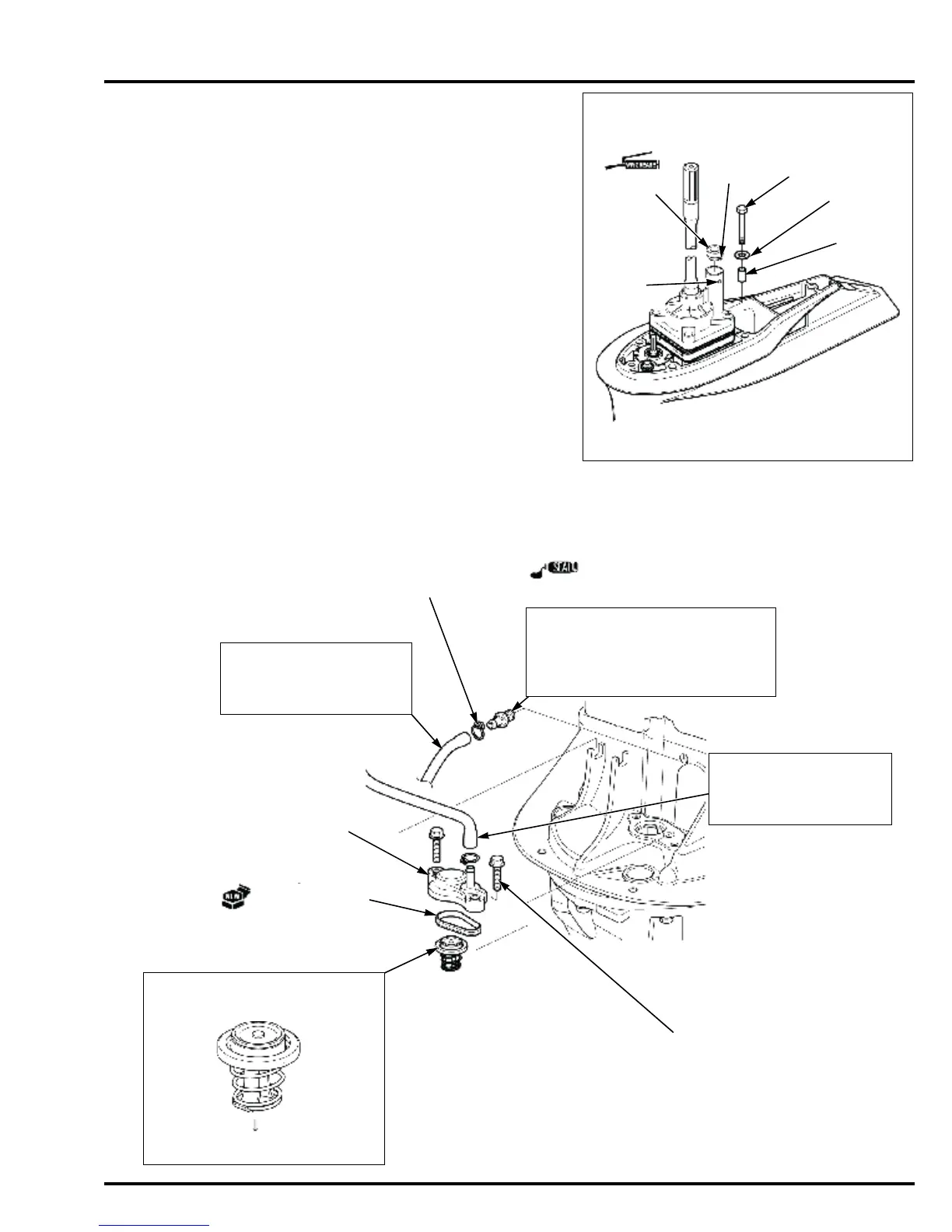
RELIEF VALVE REMOVAL/INSTALLATION
Remove the cylinder head (page 14-19).
TORQUE: 19.7 N·m (2.0 kgf·m, 15 lbf·ft)
INSTALLATION:
Check the water check tube for
deterioration and cracks.
Replace if necessary.
WATER CHECK TUBE
TUBE CLIP (B 10) (2)
WATER TUBE JOINT
INSTALLATION:
Apply liquid gasket (Threebond® #1215
or equivalent) to the threads.
TORQUE:
9 N·m (0.92 kgf·m, 6.6 lbf·ft)
INSTALLATION:
Check the water tube B for
deterioration and cracks.
Replace if necessary.
WATER TUBE B
BOLT (6 x 22 mm) (2)
RELIEF VALVE COVER
COVER O-RING
RELIEF VALVE
INSTALLATION:
Note the installation direction.
MOUNT CASE SIDE
 Loading...