95
DISPLAYING THE MEASUREMENT RESULT
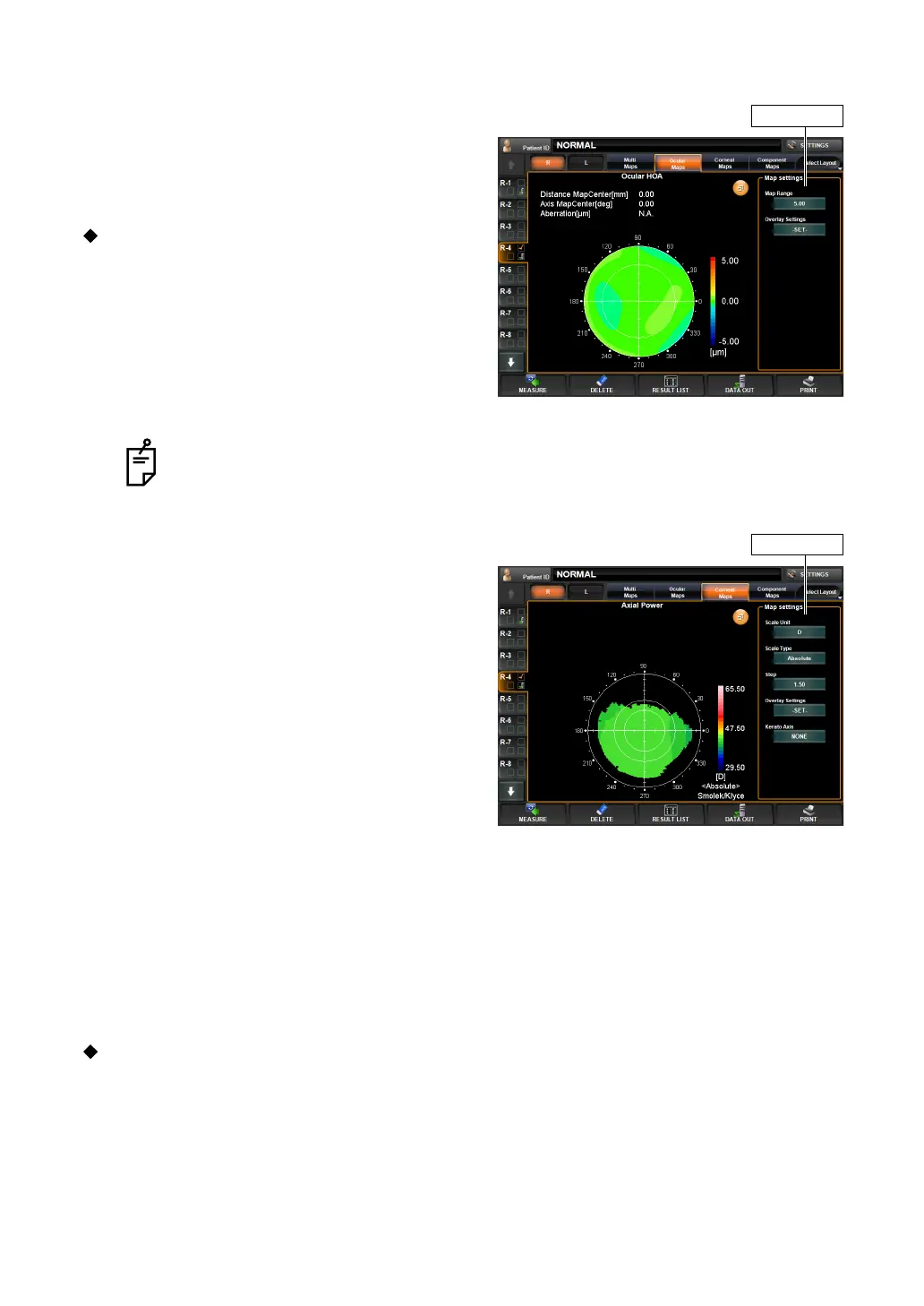
EXAMPLE: HIGH ORDER ABERRATION
The following items are displayed at the top left
of the screen:
• Coordinate values (distance and angular
direction from the center)
• Aberration value
Near the "Map Setting" displayed on the
right, the following display setting can be
done:
• Display step
• Overlay setting
The contents and method of setting are the
same as "Example: Total Aberration."
EXAMPLE: AXIAL POWER MAP
The following items are displayed at the top left
of the screen:
• Distance Map Center To Pupil Center:
Pupil coordinate values (distance from the
pupil center)
• Axis Map Center To Pupil Center:
Pupil coordinate values (angular direction
from the pupil center)
• Distance Map Center:
Cornea coordinate values (angular direction
from the cornea center)
• Distance Pupil Center:
Cornea coordinate values (distance from the
cornea center)
• Axis Map Center:
Pupil-cornea coordinate difference (distance)
• Axis Pupil Center:
Pupil-cornea coordinate difference (angular direction)
• Power:
Corneal refractive power
•Radius:
Corneal curvature radius.
Near the "Map Setting" displayed on the right, the following display setting can be done:
Items set by "Map Setting," displayed on the right side of the enlargement display,
can also be set by the items of "DISPLAY" of the "SETTINGS screen." See "
DIS-
PLAY SETTING (DISPLAY)" on page 142.
Map settings
Map settings