RemovingtheFrontSteeringFork(continued)
8.Removetheange-headscrew(item3inFigure271),spindlecap,and
retainingringthatsecurethesteeringforkshaftintotheaxletube.Slide
thesteeringforkoutoftheaxletube.
9.Locateandretrievetheupperandlowerthrustwashersfromthesteering
forkspindle.
10.Ifnecessary,removetheangenut(item16inFigure271),3washers,
spacer,bolt,andange-headscrewthatsecuresthetargetbrackettothe
steeringforkassembly.
11.Cleanthesteeringforkspindle(item3inFigure273).Inspecttheshaftfor
wearandreplacethesteeringforkspindleiftheshaftiswornordamaged.
12.Cleanandinspectthethrustwashersandangebushingsintheaxle.
Replacethecomponentsthatarewornordamagedasnecessary;referto
ServicingtheSteeringAssemblyBushings(page6–38).
InstallingtheFrontSteeringFork
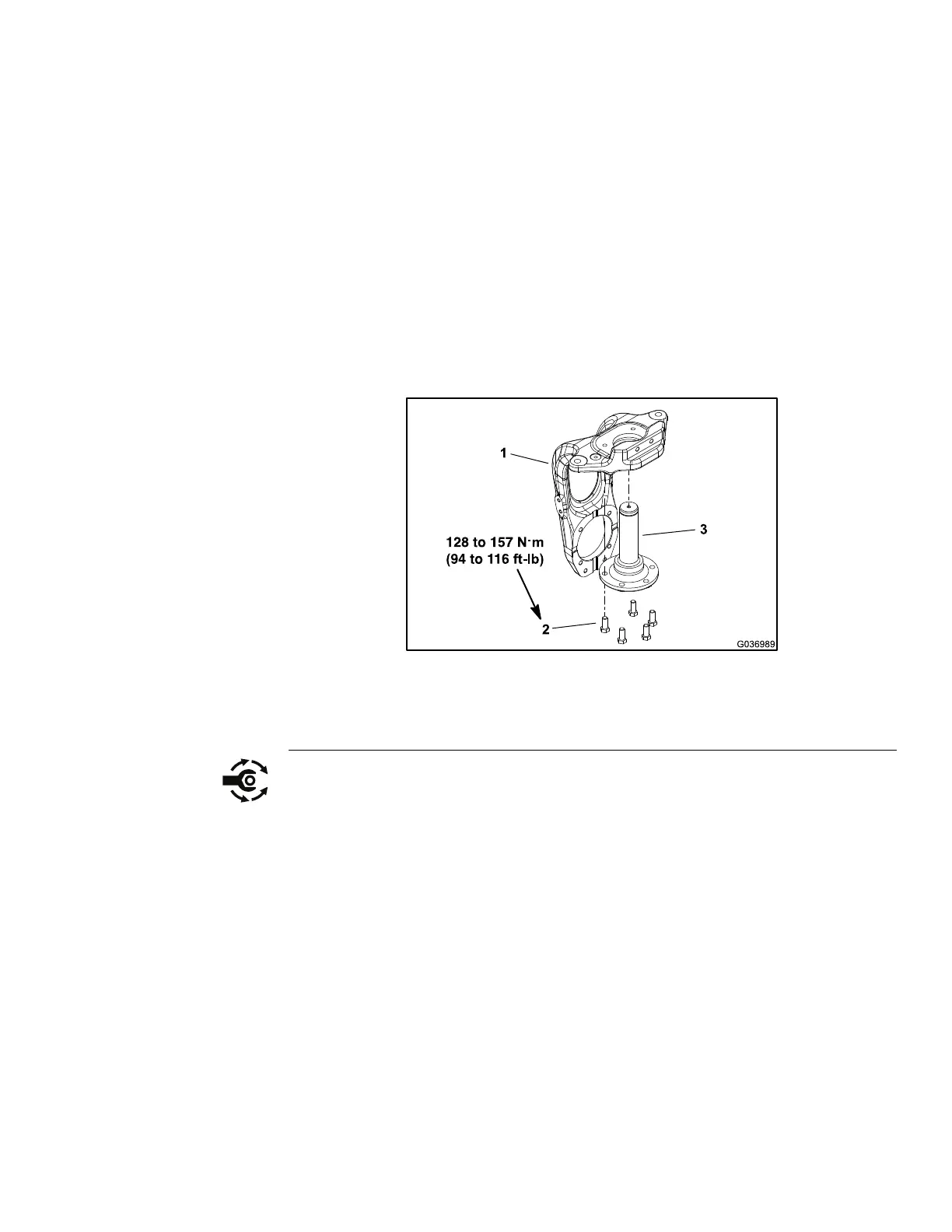
g036989
Figure273
1.Steeringfork3.Steeringforkspindle
2.Bolt(5each)
1.Ifthespindlewasremovedfromthesteeringfork,torquethe5boltsto128to
157N∙m(94to116ft-lb)duringassembly.
2.Applyalightcoatingofgreasetothesteeringforkspindle(item3inFigure
273).
3.Ifremoved,securethetargetbrackettothesteeringforkassemblywiththe
angenut(item16inFigure271),3washers,spacer,bolt,andange-head
screw.
4.Installthelower6.3mm(0.25inch)thrustwasher(item15inFigure271)
ontothesteeringforkspindleandslidethespindleupthroughtheaxletube.
5.Holdthesteeringforkinplaceandinstalltheupper1.3mm(0.062inch)
thrustwasherandretainingringontotheendofthespindle.Ensurethatthe
retainingringisfullyseatedinthespindlegroove.
6.Placethespindlecap(item4inFigure271)tothetopofthesteeringfork
spindleandsecurethespindlecapwiththeange-headscrew.
7.Securethewheelmotorassemblyasfollows:
A.Slidethewheelmotorassembly(withthewheelhubandhydrauliclines
attached)intothesteeringfork.
Groundsmaster360
Page6–29
Chassis:ServiceandRepairs
16225SLRevC

 Loading...


