Workman HDX Auto Page 5 − 43 Chassis
5. Remove knobs from control levers (Fig. 36).
6. Remove six (6) washer head screws that secure
center console control plate assembly to seat base. Re-
move center console control plate assembly.
7. Remove four (4) washer head screws that secure
shift plate (item 5) to seat base. Lift shift plate from seat
base, carefully unplug plate connector from vehicle wire
harness and remove shift plate.
8. Remove four (4) socket head screws that secure
each seat to vehicle. Lift both seats from vehicle.
9. Carefully lift seat base from vehicle.
Installation (Fig. 33)
1. Lower seat base to vehicle while guiding control lev-
ers through seat base opening.
2. Secure seats to vehicle with removed fasteners.
3. Secure center console control plate to seat base with
removed screws. Torque screws a maximum of 12 in−lb
(1.3 N−m). Make sure that lift lever can be moved in con-
trol plate slot to allow correct operation of lift lock.
4. Plug shift plate (item 5) connector into vehicle wire
harness. Position shift plate to seat base and secure
with four (4) washer head screws. Torque screws a max-
imum of 12 in−lb (1.3 N−m).
5. Install knobs on control levers.
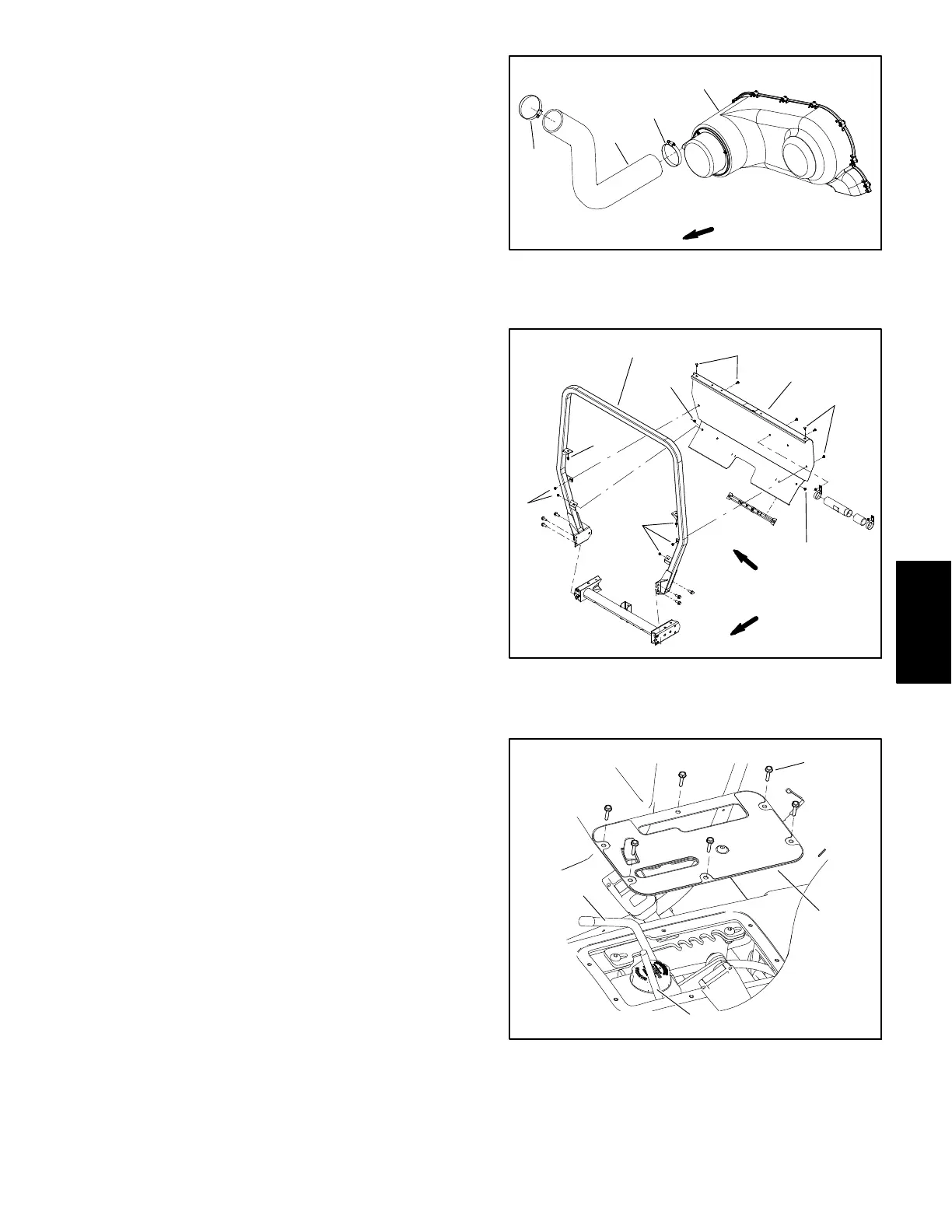
6. Install ROPS cover to vehicle (Fig. 35).
7. Secure engine coolant overflow tank into slots in rear
of ROPS cover.
8. Install CVT intake hose to ROPS cover and CVT en-
closure cover (Fig. 34). Secure intake hose with hose
clamps.
9. Lower bed (if installed).
Figure 34
1. CVT enclosure cover
2. CVT intake hose
3. Hose clamp
1
2
3
3
FRONT
Figure 35
1. ROPS frame
2. Carriage screw (6)
3. Flange nut (6)
4. ROPS cover
1
2
3
4
2
3
3
2
2
FRONT
RIGHT
Figure 36
1. Control plate
2. Screw (6)
3. Speed range lever
4. Hydraulic lift lever
1
2
3
4
Chassis