Workman HDX Auto Page 4 − 29 Drive Train
Disassembly (Fig. 31)
1. Remove lock nut (item 3) from each of the shoulder
screws (item 2). Discard lock nuts after removal.
2. Slide shoulder screw from each of the clutch weights
(item 4) and then remove weights from clutch.
3. Clean all dust and debris from clutch components
with a soft bristle brush. If necessary, use water to re-
move dirt and dry immediately with compressed air to re-
move all dirt and water. Remove any remaining debris
with a fast drying contact or brake parts cleaner. Focus
debris removal on and around moving components.
Inspection
NOTE: If primary clutch wear or damage occurs, clutch
replacement may be necessary. Refer to your parts cat-
alog to identify individual primary clutch components
that are available.
1. Inspect the tapered ends of the engine crankshaft
and stationary sheave of primary clutch. If either is se-
verely damaged, replace component as damage to the
taper will allow loosening of the clutch during operation.
2. Clean and inspect shoulder screws (item 2). If the
shoulder area of the screws is worn or if the threads are
damaged, replace the screws.
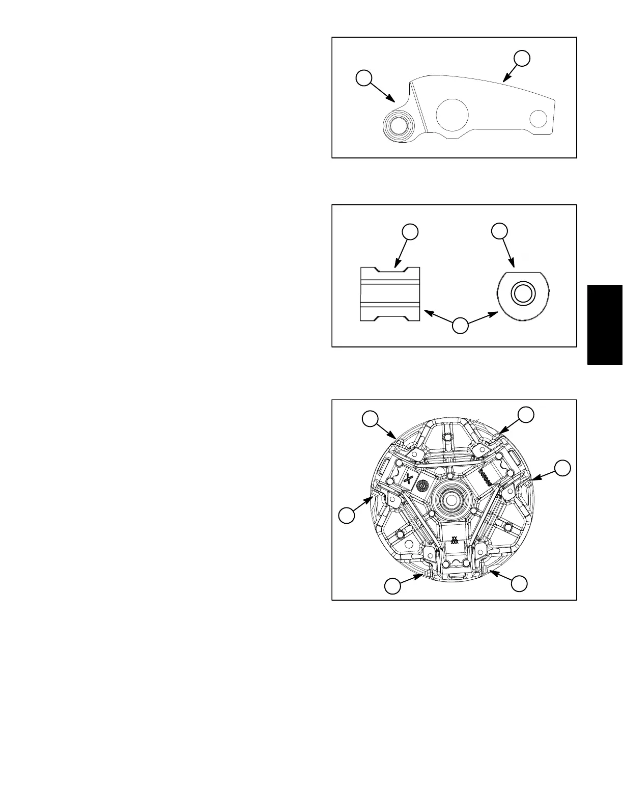
3. Check the contact surface of the clutch weights
(Fig.4). If surface is worn or damaged, replace all three
(3) clutch weights as a set.
4. Check the rollers in the spider assembly for binding
or wear (Fig. 33). If binding or uneven wear is found, re-
place primary clutch assembly.
5. Check the belt contact surfaces of the movable and
stationary sheaves. Remove any belt material from
sheave faces with a fine abrasive pad or fine steel wool.
If sheave surfaces are worn, replace primary clutch.
Assembly (Fig. 31)
IMPORTANT: For proper clutch operation, DO NOT
lubricate clutch components during assembly.
IMPORTANT: To maintain the balance of the clutch,
all shoulder screws must be installed with their
threads pointing in a clockwise direction (Fig. 34).
1. Position clutch weights to moveable sheave and
slide shoulder screw into sheave and weight. Make sure
that screw threads are pointing in a clockwise direction.
2. Install new lock nuts on the shoulder screws. DO
NOT reuse removed lock nuts. Tighten nuts until they
contact screw shoulder and then torque nuts from 40 to
50 in−lb (4.6 to 5.6 N−m).
1. Clutch weight 2. Contact surface
Figure 32
2
1
1. Roller
2. Weight contact surface
3. Roller uneven wear
Figure 33
2
1
3
1. Shoulder screw head 2. Lock nut
Figure 34
2
1
1
1
2
2
SafetyProduct Records
Drive Train