EasyManuals Logo

Toshiba B-FV4 Series User Manual

Toshiba B-FV4 Series
302 pages
To Next Page IconTo Next Page
To Previous Page IconTo Previous Page
Page #45 background imageLoading...
Page #45 background image
2. ELECTRONICS SPECIFICATIONS EO18-33030
2.3 Main PC Board Connector Pin Assignment
2-8
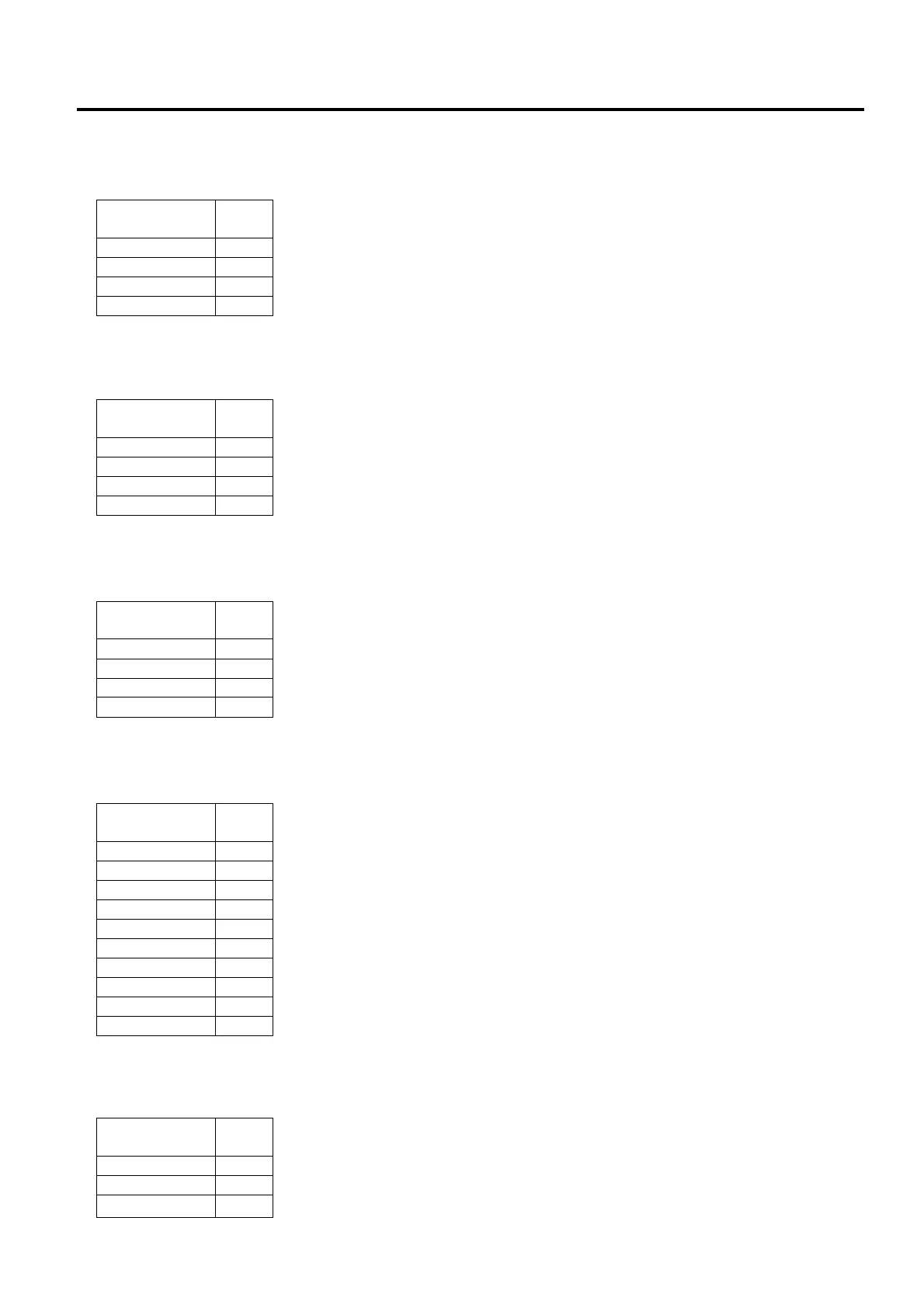
J12 (Ribbon Sensor): This connector is connected to the Ribbon Sensor.
J13 (Black Mark Sensor): This connector is connected to the Black Mark Sensor.
J14 (Peeler Sensor): This connector is connected to the Peel-off Module.
J15 (RF Module): This connector is connected to the RF Module.
P1 (DC Jack): This DC jack is connected to the DC plug of the AC adaptor.
Signal
Pin
No.
+5V 1
REF I 2
+3V3 3
REF MEDIA 4
Signal
Pin
No.
+5V 1
GND 2
+3V3 3
PEELR 4
Signal
Pin
No.
+5V 1
GND 2
+3V3 3
RIBBON 4
Signal
Pin
No.
+3V3 1
GND 2
PB nCTS 3
PB nRTS 4
PB RXD 5
PB TXD 6
BT DISCON 7
BT CON IND 8
GND 9
+3V3 10
Signal
Pin
No.
Power 1
GND 2
GND 3

Table of Contents

Other manuals for Toshiba B-FV4 Series

Questions and Answers:

Question and Answer IconNeed help?

Do you have a question about the Toshiba B-FV4 Series and is the answer not in the manual?

Toshiba B-FV4 Series Specifications

General IconGeneral
Resolution203 dpi
Print MethodThermal Transfer / Direct Thermal
2D CodesData Matrix, PDF417, QR Code, Maxi Code
Operating Temperature5 – 40 °C
Storage Temperature-20 – 60 °C
Power Supply100-240 VAC, 50/60 Hz
InterfacesUSB, Serial (RS-232)
Media Width25.4 – 112 mm

Related product manuals