2. ELECTRONICS SPECIFICATIONS EO18-33030
2.3 Main PC Board Connector Pin Assignment
2-6
2.3 Main PC Board Connector Pin Assignment
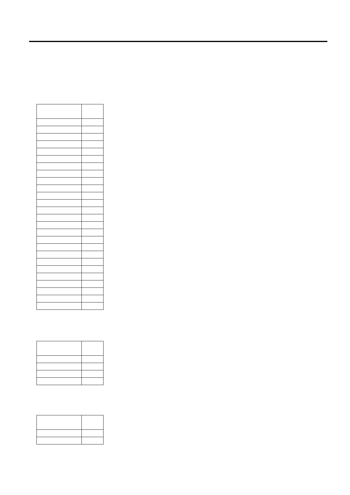
2.3.1 Pin Assignment for B-FV4T-GS/TS
J1 (Print Head): This connector is connected to the print head.
The voltages and signals for controlling the print head are input/output
into/from the connector.
J4 (Stepping Motor): This connector is connected to the Stepping Motor.
J5 (Feed Gap Sensor (Upper)): This connector is connected to the Feed Gap Sensor (Upper).
Signal
Pin
No.
GND 1
GND 2
+24V 3
+24V 4
+24V 5
+24V 6
+24V 7
+24V 8
DI 9
DO 10
nLAT 11
+5V 12
GND 13
GND 14
STB1 15
TM 16
+24V 17
+24V 18
GND 19
GND 20
CLK 21
STB2 22
GND 23
GND 24
GND 25
GND 26
Signal
Pin
No.
A 1
nA 2
B 3
nB 4
Signal
Pin
No.
Control 1
5V 2
 Loading...