EasyManuals Logo

Toshiba B-FV4 Series User Manual

Toshiba B-FV4 Series
302 pages
To Next Page IconTo Next Page
To Previous Page IconTo Previous Page
Page #63 background imageLoading...
Page #63 background image
3. REPLACING THE IMPORTANT PARTS EO18-33030
3.1 Replacing the Parts for B-FV4T-GS/TS
3-5
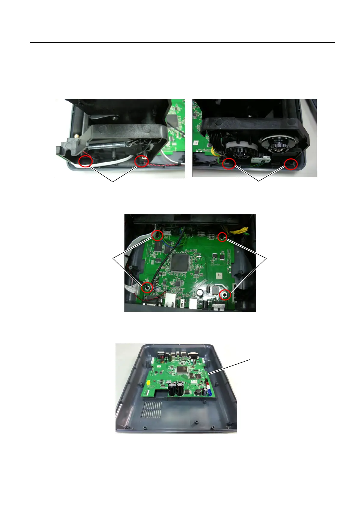
3.1.2 Replacing the Main PC Board
1. Refer to Section 3.1.1 to remove the mid cover.
2. Use a Phillips screwdriver to remove the 4 screws from the printer module.
3. Disconnect all cables from the main PC board and then remove the 4 screws on the main PC board.
4. Remove the printer module and then take off the main PC board.
5. Replace the main PC board with a new one and then reassemble it in the reverse order of removal.
NOTE: Refer to 2.4 DIP Switch about the DIP switch setting of the main PC board.
Screw
Screw
Screw
Main PC Board
[Printer Module Right Side] [Printer Module Left Side]
Screw

Table of Contents

Other manuals for Toshiba B-FV4 Series

Questions and Answers:

Question and Answer IconNeed help?

Do you have a question about the Toshiba B-FV4 Series and is the answer not in the manual?

Toshiba B-FV4 Series Specifications

General IconGeneral
Resolution203 dpi
Print MethodThermal Transfer / Direct Thermal
2D CodesData Matrix, PDF417, QR Code, Maxi Code
Operating Temperature5 – 40 °C
Storage Temperature-20 – 60 °C
Power Supply100-240 VAC, 50/60 Hz
InterfacesUSB, Serial (RS-232)
Media Width25.4 – 112 mm

Related product manuals