EasyManuals Logo

Toshiba B-FV4 Series User Manual

Toshiba B-FV4 Series
302 pages
To Next Page IconTo Next Page
To Previous Page IconTo Previous Page
Page #80 background imageLoading...
Page #80 background image
3. REPLACING THE IMPORTANT PARTS EO18-33030
3.2 Replacing the Parts for B-FV4D-GS/TS
3-22
3.2.7 Replacing the Feed Gap Sensor (Upper)
1. Refer to Section 3.2.4 to take off the mid cover.
2. Refer to Section 3.2.1 to take off the top cover.
3. Refer to Section 3.2.9 to take out the print head assembly.
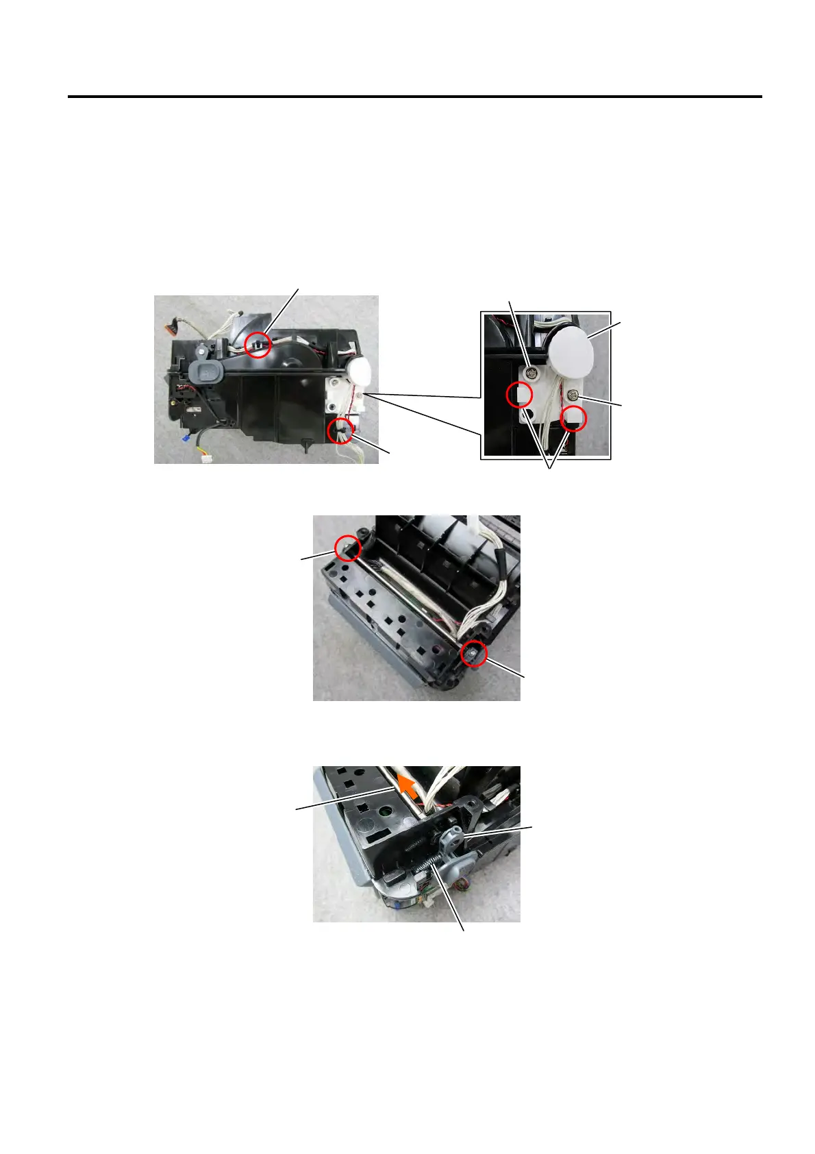
4. Cut the 2 cable ties.
5. Use a Phillips screwdriver to remove the 2 screws and then release the 2 latches to take off the hinge
cover.
6. Use a Phillips screwdriver to remove the 2 screws.
7. Slide the shaft in the direction indicated by the arrow and then take off the lock release portion and
remove the spring at the right side of the printer.
Cable Tie
Cable Tie
Screw
Screw
Lock Release Portion
Spring
Shaft
Latch
Screw
Screw
Hinge Cover

Table of Contents

Other manuals for Toshiba B-FV4 Series

Questions and Answers:

Question and Answer IconNeed help?

Do you have a question about the Toshiba B-FV4 Series and is the answer not in the manual?

Toshiba B-FV4 Series Specifications

General IconGeneral
Resolution203 dpi
Print MethodThermal Transfer / Direct Thermal
2D CodesData Matrix, PDF417, QR Code, Maxi Code
Operating Temperature5 – 40 °C
Storage Temperature-20 – 60 °C
Power Supply100-240 VAC, 50/60 Hz
InterfacesUSB, Serial (RS-232)
Media Width25.4 – 112 mm

Related product manuals