3. REPLACING THE IMPORTANT PARTS EO18-33030
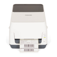
3.2 Replacing the Parts for B-FV4D-GS/TS
3-25
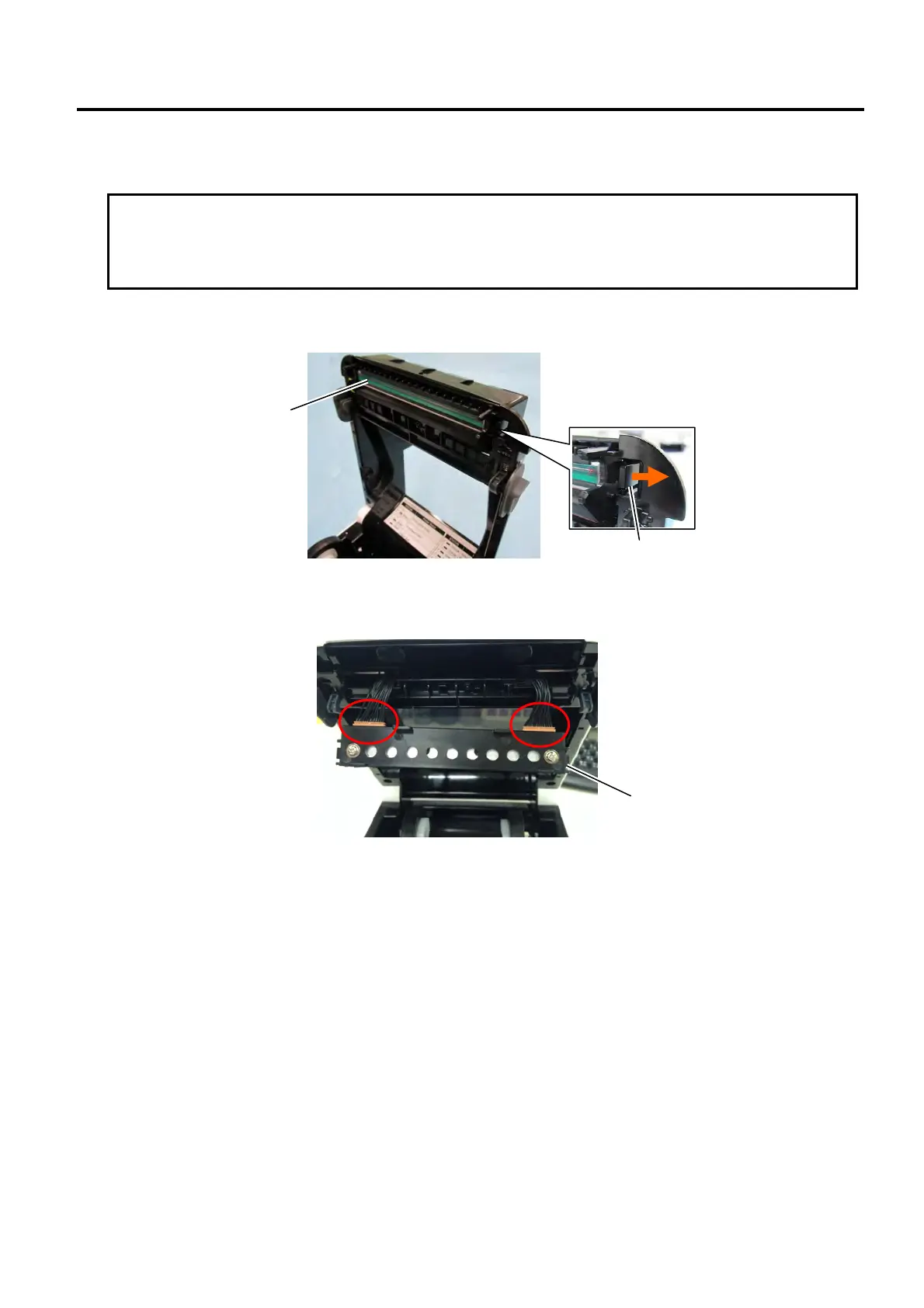
3.2.9 Replacing the Print Head Assembly
1. Open the top cover.
2. Pull the latch to the left until the left part of the print head assembly is released.
3. Disconnect the 2 cables to take out the print head assembly.
4. Replace the print head assembly with a new one and then reassemble it in the reverse order of
removal.
NOTE: Do not disassemble a print head assembly containing a bracket.
5. After replacing, perform a diagnostic test print or print a sample label to make sure the printer is
performing correctly regarding the following points.
Printing is performed correctly.
No dot missing is generated.
None of blurred printing, staining, chipped bar code or characters, wrinkling, smudging, uneven
printing, etc. is generated.
Reading the bar code is possible.
Latch
Print Head Assembly
CAUTION!
1. NEVER touch the element when handling the print head.
2. NEVER touch the connector pins. This might cause the print head to break down due to static
electricit
.
Print Head Assembly
 Loading...