115
The configuration procedure for switch E and F is the same with that for switch D.
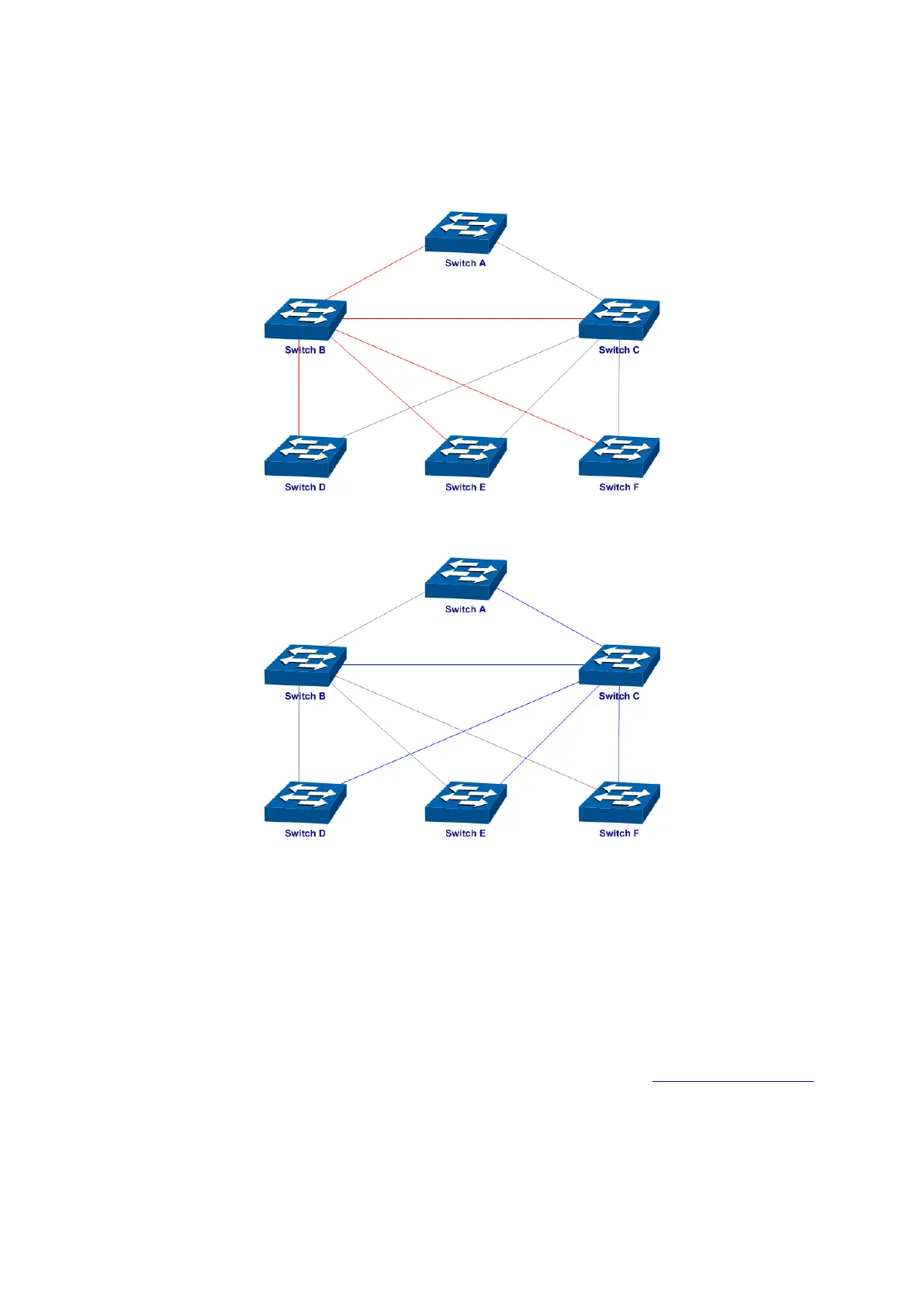
The topology diagram of the two instances after the topology is stable
For Instance 1 (VLAN 101, 103 and 105), the red paths in the following figure are connected
links; the gray paths are the blocked links.
For Instance 2 (VLAN 102, 104 and 106), the blue paths in the following figure are connected
links; the gray paths are the blocked links.
Suggestion for Configuration
Enable TC Protect function for all the ports of switches.
Enable Root Protect function for all the ports of root bridges.
Enable Loop Protect function for the non-edge ports.
Enable BPDU Protect function or BPDU Filter function for the edge ports which are connected to
the PC and server.
Return to CONTENTS