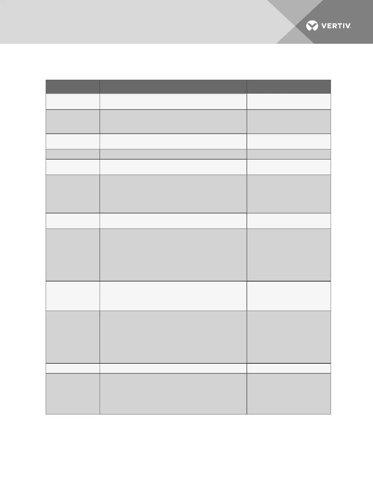
Item Description For more information, see:
A - Power On/Off
switch
Power switch for the controller board. When switched off, the
battery pack is disabled.
Connect Power to the Liebert
AC8 on page14
B - Battery pack
Provides battery backup during a power loss to maintain normal
operation of the panel for a minimum of 10 minutes. The analog
inputs will not be functional during a power loss (P/N 133455P1).
Connecting the Battery Pack
on page16
Connect Battery on page85
C - EIA422 LEDs
Indicates the connection status between the Liebert AC8 and
Liebert SiteScan Web
™
.
LED Indicators on page8
D - Audible horn
Provides audible notification when an alarm occurs. N/A
E - Audible horn
jumper
Jumper to disable the audible horn (factory default is enabled). N/A
F - Common Alarm
connectors
The two common alarm connections are used to connect to a
secondary warning device such as a horn, light or Building
Management System (BMS). When an alarm is present, the
contacts close and the external warning device is activated/notified.
The common alarm contacts may be configured to be reset with the
Silence button/command.
3.0: Wiring and Connections
Connecting Common Alarm
Outputs on page27
Setup System - Setup
Common Alarm on page60
G - Digital output
status LEDs
Each output has an LED to indicate its status: ON/OFF
(energized/de-energized).
LED Indicators on page8
H - Control relay
outputs
Each of the two output connections is a two-state point: ON/OFF
(energized/de-energized). Digital and analog inputs may be
mapped to either or both relays to trigger change in state.
An example of a control relay output point is a humidity lock-out.
3.0: Wiring and Connections
Connecting Control Relay
Outputs on page23
View Control Status on
page47
Setup System - Setup I/O
Matrix on page101
I - Manual Override
Switch (outputs)
Placing the switch in the ON position will turn ON, or energize, all
eight outputs simultaneously. This switch removes all automatic
output control from the Liebert AC8.
The factory default is OFF (outputs controlled by programming).
Override Output on page103
J - Digital output
connectors
Each of the eight output connections is a two-state point: ON/OFF
(energized/de-energized).
An example of a field digital output point is an air unit On/Off control
circuit.
3.0: Wiring and Connections
Connecting Digital Outputs on
page21
View Output Status on
page43
Setup System - Setup Outputs
on page70
K - Status LEDs
Indicates the operational status of the controller board. LED Indicators on page8
L - Digital output
loss-of-power jumper
One of eight output jumpers. Each digital output has a jumper to set
the fail-safe position of the output point when power fails. The OFF
position makes the contact Normally Open (factory default). The
ON position makes the contact Normally Closed.
Note: The jumper position has no effect on the contact when the
Liebert AC8 has power.
Setting the Digital Output
Jumpers on page21
Configure Output for Loss of
Power (“Fail-Safe”) on
page72
Table 1.1
Controller board components
Vertiv | Liebert® AC8 User Manual | 6