Operation
1203−1/A1
Winterthur Gas & Diesel Ltd.
1/ 2
Thrust Bearing
1. General
The thrust bearing is installed at the driving end of the engine. The thrust bearing
flange transmits the force from the propeller through the thrust pads into the bedplate.
The arbor supports (4, Fig. 1) prevent axial movement of the thrust pads.
There are six thrust pads (5 and 9) on each side of the thrust bearing flange
(10, Fig. 2). The thrust pads absorb the axial force from the crankshaft and propeller.
The crankshaft gear wheel moves the intermediate wheel of the supply unit.
1.1 Engines with Fixed Pitch Propellers
For clockwise and counterclockwise rotation, six thrust pads are installed on each
side of the thrust bearing flange. The thrust pads adapt to the clockwise or
counterclockwise rotation.
1
2
3
4
6
5
7
OI
I
I
WCH01198
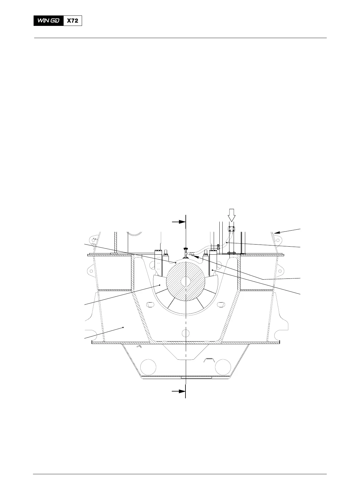
Fig. 1: Cross Section
1 Column 6 Thrust pad
2 Oil pipe 7 Bearing cover
3 Nozzle
4 Arbor support
5 Bedplate OI Bearing oil inlet
2014